Mountainous area multifunctional bridge conveying-erecting machine and bridge-erecting method

A girder transporter and multi-functional technology, applied in bridge construction, erection/assembly of bridges, bridges, etc., to achieve the effects of simplifying procedures, improving stability, and improving efficiency

Active Publication Date: 2010-06-16
北京万桥兴运工程技术有限公司
View PDF6 Cites 9 Cited by
  • Summary
  • Abstract
  • Description
  • Claims
  • Application Information

AI Technical Summary

Problems solved by technology

[0003] The technical problem to be solved by the present invention is to provide a bridge that can effectively solve the problems of bridging in the tunnel and the first hole of the tunnel exit and erecting a bridge with a small radius of curvature, so that under the condition of poor construction conditions in mountainous areas, the It is more convenient, flexible, time-saving, labor-saving, and efficient to transfer the construction site, turn around and turn around, and erect isolated bridges and wild bridges. The multifunctional beam transporter and bridge erection method in mountainous areas

Method used


Image

  • Mountainous area multifunctional bridge conveying-erecting machine and bridge-erecting method
  • Mountainous area multifunctional bridge conveying-erecting machine and bridge-erecting method
  • Mountainous area multifunctional bridge conveying-erecting machine and bridge-erecting method

Examples


Embodiment Construction

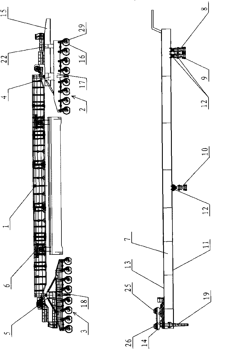
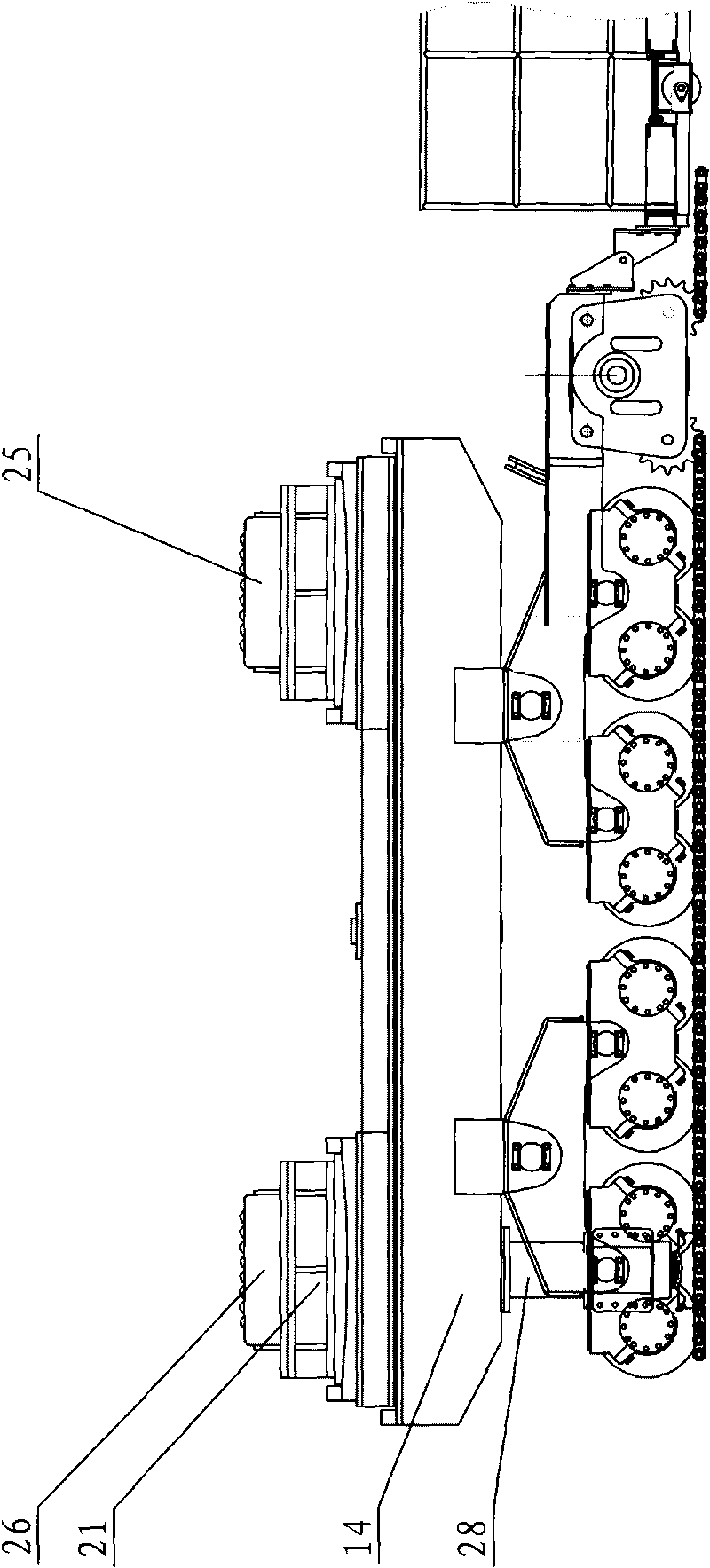
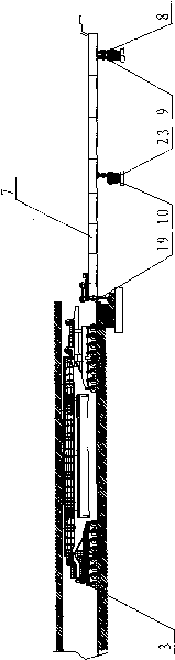
[0037] like figure 1 As shown, the multifunctional beam transporting machine in the mountainous area of ​​the present invention includes a beam transporting machine and a lower guide beam machine, and the beam transporting machine includes a beam transporting machine and a lower guiding beam machine, and the beam transporting machine includes a main girder 1 and front and rear beams. Traveling wheel group 2,3, front and rear traveling wheel group 2,3 comprise some wheels to 16 and front and rear longitudinal vehicle frame 17,18, be provided with lifting oil cylinder 29 between wheel to 16 and front longitudinal vehicle frame 17. Front and rear longitudinal vehicle frames 17, 18 are equipped with front and rear support frames 4, 5 respectively, the front support frame 4 is a saddle type, and the upper ends of the front and rear support frames 4, 5 are respectively connected with the two ends of the main beam 1 by pins. The shafts are hinged, and the bolts on the front support f...


PUM


Abstract

The invention provides a mountainous are a multifunctional bridge conveying-erecting machine, which relates to bridge-erecting equipment. The invention aims to provide a mountainous area multifunctional bridge conveying-erecting machine which can effectively solve the problem of erecting bridges in tunnels and first holes outside tunnel portals and can erect the bridges with small curve radius, as well as a bridge-erecting method. The multifunctional bridge conveying-erecting machine comprises a bridge conveying-erecting machine and a lower beam-guiding machine, wherein the bridge conveying-erecting machine comprises a girder, a front moving wheel set and a back moving wheel set; the front and back moving wheel sets comprise a plurality of wheel pairs, a front longitudinal frame and a back longitudinal frame; the beam-guiding machine comprises a guide beam, a front roller support leg, a middle roller support leg and a back roller support leg; the top of the guide beam is provided witha movable bridge-erecting trolley; a lead beam horizontally extending forwards is arranged on a front support frame on the front longitudinal frame; at least one fulcrum and a brake mechanism are arranged on the bridge-erecting trolley; the fulcrum can slide backwards along the bottom of the lead beam; and the wheel pairs of the front moving wheel set are controlled by an electro-hydraulic systemto be gradually lifted in the moving process so as to change the front support force of the girder from the front moving wheel set to the bridge-erecting trolley.

Description

technical field [0001] The invention relates to bridge erecting equipment, in particular to an integrated bridge erecting machine for transporting and erecting girders. Background technique [0002] At present, the existing integrated bridge erecting machine for transporting and erecting girders, such as the bridge erecting machine disclosed in Chinese utility model patent ZL200420115944. , it is necessary to return the guide beam several times so that the front wheel set of the girder erecting machine can fall on the bridge surface, and the guide beam is longer and located at a certain distance from the bridge surface, which leads to a large limit on the curve radius when erecting a curved bridge. There are many procedures in the erection process, which is time-consuming and laborious, and the efficiency is low. In addition, when the first hole concrete beam is erected at the exit of the tunnel, because the lifting height of the concrete beam in the tunnel is limited by th...

Claims


Application Information

Patent Timeline
IPC IPC(8): E01D21/00
Inventor 刘亚滨潘达张福德张胜军于文涛袁付春
Owner 北京万桥兴运工程技术有限公司
Why Eureka
Try Eureka