
Labyrinth minimum flow control valve

A minimum flow, labyrinth technology, applied in the valve's device for absorbing fluid energy, lift valve, valve details, etc., to achieve the effect of long service life

Active Publication Date: 2011-12-21
SHANGHAI PINGAN HIGH PRESSURE REGULATING VALVE FACTORY
View PDF0 Cites 0 Cited by
  • Summary
  • Abstract
  • Description
  • Claims
  • Application Information

AI Technical Summary

Problems solved by technology

[0005] The technical problem to be solved by the present invention is to overcome the shortcomings of the existing minimum flow control valve and provide a labyrinth minimum flow control valve

Method used


Image

  • Labyrinth minimum flow control valve
  • Labyrinth minimum flow control valve
  • Labyrinth minimum flow control valve

Examples


Embodiment Construction

[0025] In order to make the technical means, creative features, goals and effects achieved by the present invention easy to understand, the present invention will be further described below in conjunction with specific illustrations.

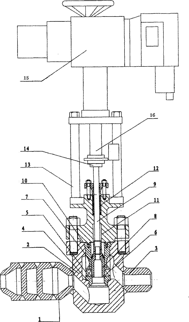
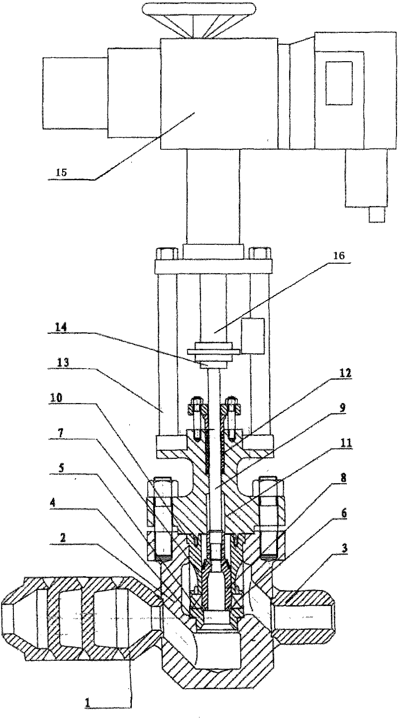
[0026] see figure 1 , The labyrinth-type minimum flow control valve mainly consists of a valve body 2, a valve cover 11, a bracket 13 and an electric actuator 15.

[0027] The two ends of the valve body 2 are provided with water inlet and outlet ports 3, and the water inlet and outlet ports 3 are connected to the water inlet and outlet channels in the valve body, and the water inlet and outlet channels are arranged in a staggered position with each other. A throttling device 1 is arranged at one end of the water inlet and outlet 3, and the throttling device 1 is used to reduce the flow velocity of the medium and play a role of damping. The other end is small, so it can reduce the flow rate.

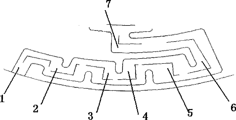
[0028] A valve seat 5, a labyrinth disc 6, a flow e...


PUM


Abstract

The labyrinth-type minimum flow control valve includes a valve body, a valve core and a valve seat arranged in the valve body, and a water inlet and outlet on the valve body. . The labyrinth-type minimum flow control valve of the present invention adopts the design of variable-diameter and unequal flow passages, so that high-pressure liquid flows along the middle of the flow passage, preventing turbulent flow from flowing along the wall, and has the advantages of anti-cavitation, low noise, and high pressure difference. Two characteristics, long service life.

Description

technical field [0001] The patent of the present invention relates to the technical field of thermal fluid systems, in particular to a minimum flow control valve for power plant boiler feed water pumps. The valve is mainly used for pressure regulation and reducing cavitation, which can greatly reduce noise and prolong service life. Background technique [0002] When the power station is in peak-shaving operation and overload state, when the required flow rate is less than the specified value, the temperature and pressure of the liquid flow will rise sharply, which will cause the liquid in the feed water pump to vaporize, and even cause the feed water pump to fail to work. The automatic function of the minimum flow control valve is that when the output flow of the feed water pump is less than a certain value, it will be automatically opened immediately, and the excess flow will be diverted to the deaerator, so that the feed water pump can run under reliable conditions, effect...

Claims


Application Information

Patent Timeline
Patent Type & Authority Patents(China)
IPC IPC(8): F16K47/02F16K47/08F16K27/00F16K1/36F16K31/02
Inventor 陆亚安蔡宝根陆耀威朱峰范国良
Owner SHANGHAI PINGAN HIGH PRESSURE REGULATING VALVE FACTORY
Learn More