
Deflector

A flow guide device and axial flow technology, applied in the direction of airflow control components, etc., can solve the problems of different design methods, inability to convert fans, and failure to improve the efficiency of axial flow fans, etc., to achieve high efficiency and increase pressure rise Effect

Active Publication Date: 2011-09-14
四川长虹空调有限公司
View PDF2 Cites 0 Cited by
  • Summary
  • Abstract
  • Description
  • Claims
  • Application Information

AI Technical Summary

Problems solved by technology

Although the patent application stipulates that the radial strips have corresponding constraints on the blown airflow and curvature at the position of 70-80% of the outer diameter of the fan, that is, around the maximum velocity of the blown airflow, the design methods of axial flow fans are different at present, and different axial flow The speed distribution of the fan at the corresponding position is also different, and the rotational kinetic energy loss of the axial flow fan is not necessarily the largest loss near 70-80%, so this patent application cannot achieve the effect of improving the efficiency of various axial flow fans , it is impossible to convert the rotational kinetic energy at all positions of the fan outlet into static pressure to a greater extent, which needs further improvement

Method used


Image

  • Deflector
  • Deflector
  • Deflector

Examples


Embodiment 1

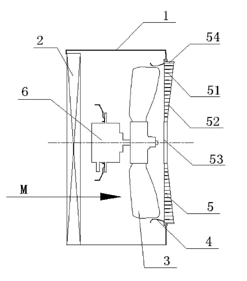
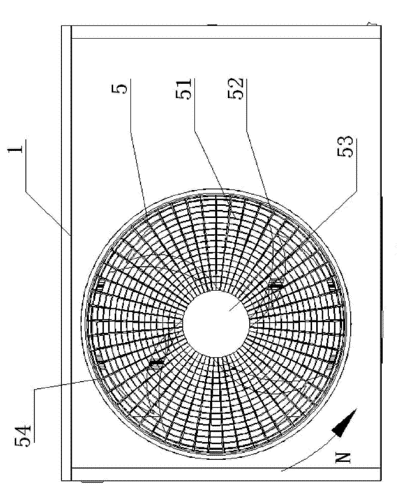
[0034] Such as figure 1 ~ Figure 5 and Picture 11 As shown, a heat exchanger 2, an axial flow fan 3, a flow guide ring 4, a flow guide device 5 and a motor 6 are provided in the box of the air conditioner outdoor unit 1. The axial flow fan 3 has 4 blades and a diameter of 460mm ; The guide device 5 is provided with 37 radial strips.

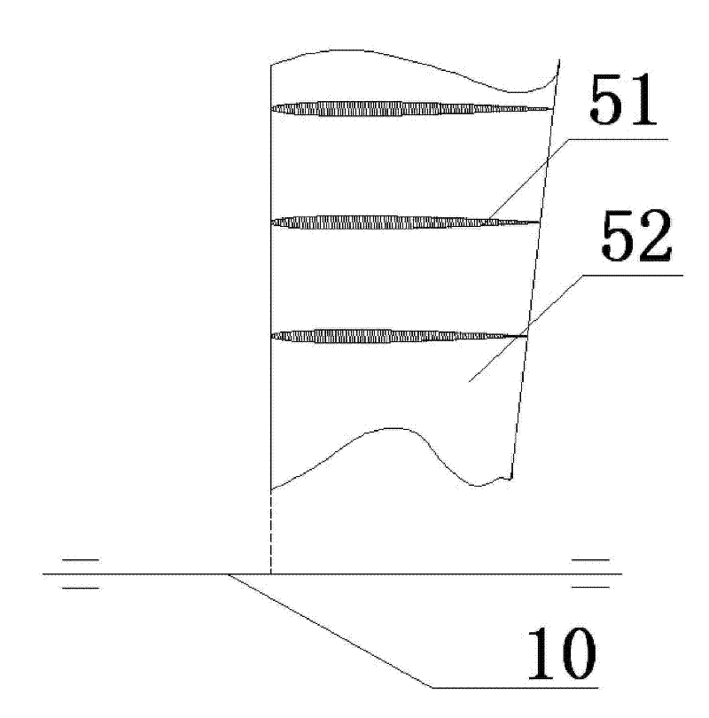
[0035] Such as figure 1 with figure 2 As shown, in the embodiment of the present invention, the diversion part and the reinforcing rib part of the diversion device 5 are made as a whole, and the diversion device 5 is composed of a plurality of radial strips 52, a plurality of concentric circular strips 51, and a central disc 53 It is composed of a circular outer frame 54 and the radial strip 52 is installed on the central disk 53 and the circular outer frame 54 which are arranged in front of the hub of the axial fan 3; the circular outer frame 54 is fixed on the first row of the outdoor unit of the air conditioner The outer side of the guide ring ...

Embodiment 2

[0048] Such as Figure 6 ~ Figure 10 As shown, the technical solution of the present invention is applied to another embodiment of the explanatory drawing of an outdoor unit of an air conditioner. The air guiding device 5 is composed of a radial strip member 7 and a concentric circular strip member 8, wherein the radial strip member 7 and the concentric circular strip member 8 is two independent parts. Among them, the number of blades of the axial flow fan 3 is 3, and the diameter is 466mm; the flow guiding device 5 is provided with 37 radial strips.

[0049] Such as Figure 7 with Picture 8 As shown, the radial strip member 7 is composed of a plurality of radial strips 71 as vane guide vanes, a circular disk 72 and a circular outer frame 73; the radial strip 71 is installed at a position corresponding to the front of the hub of the axial fan 3. The circular plate 72 and the circular outer frame 73; the circular outer frame 73 is fixed on the outside of the air outlet diversion...


PUM


Abstract

The invention discloses a deflector for a wind supply equipment, which can effectively recover the dynamic pressures of rotating flows generated by axial-flow and mixed-flow fans of different types as static pressures and comprises a plurality of radial bars connected between a central disc and a round outer frame and a plurality of concentric bars alternately connected with the plurality of radial bars, wherein the number of the radial bars is prime to the number of the blades of the fan of the wind supply equipment; and the efficiency of the wind supply equipment can be improved by optimizing the law of the change of the radial bars along with the chord length and wing chord of a radial wing-shaped structure and the included angle of the rotating shafts of an axial-flow fan. The deflector can be used in the axial-flow or mixed-flow fans of different types.

Description

Technical field [0001] The invention relates to a diversion device of an air supply device, in particular to a diversion device installed on an air supply device provided with an axial flow or mixed flow fan. Background technique [0002] The outdoor unit of the air conditioner is a blower equipped with an axial fan. The structure of the outdoor unit of the air conditioner is generally a box-shaped shell, and an axial fan is generally arranged inside. On the exhaust side of the axial fan, the box shell is provided with an exhaust port and a fan protection cover. The fan guard is a grid structure with different shapes and is made of metal and synthetic resin. [0003] It is known that the direction of the air flow after passing through the axial flow fan is not axial, that is, there is a velocity component in the circumferential direction. In order to recover this part of the energy, the industry often adds static guide vanes before and after the impeller, so that the direction of...

Claims


Application Information

Patent Timeline
Patent Type & Authority Patents(China)
IPC IPC(8): F24F13/08
Inventor 张仁亮何锦蓉
Owner 四川长虹空调有限公司
Learn More