
Patsnap Eureka
For R&D, Patsnap Eureka makes reading and utilizing patents & technical documents easy.
Patsnap Eureka AIR
Designed for self-driven R&D workflows. Generate viable solutions, solve complex R&D challenges, empower your innovation with AI.

Patsnap Eureka Materials
Designed for material experts only. Revolutionize your material R&D, from search, analyze, to developing new materials.

TechResearch
Generate reliable direction feasibility study reports for your R&D in just a few steps.

TechSeek
Discover and master advanced knowledge NOW. Basics, ideas, possibilities, all at once.

TechMind
As an expert in R&D Theories, TechMind can generates customized viable solutions instantly.

TechRisk
Analyze your overall solution with one click, know your potential R&D risks in advance.

TechMonitor
Get weekly tech updates, stay abreast of the latest tech innovations and key insights.
Intelligent fault monitoring and warning device and method of direct current (DC) panel
A technology of fault monitoring and DC screen, applied in the direction of fault location, etc., can solve problems such as failure to process fault information, complex system, etc., and achieve the effect of simplifying operation and time, and improving efficiency
- Summary
- Abstract
- Description
- Claims
- Application Information
AI Technical Summary
Problems solved by technology
Method used
Image

Examples
Embodiment 1
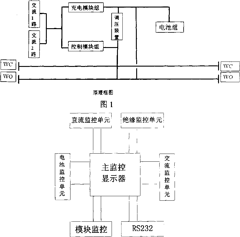
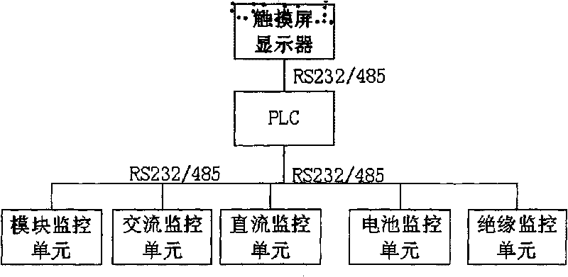
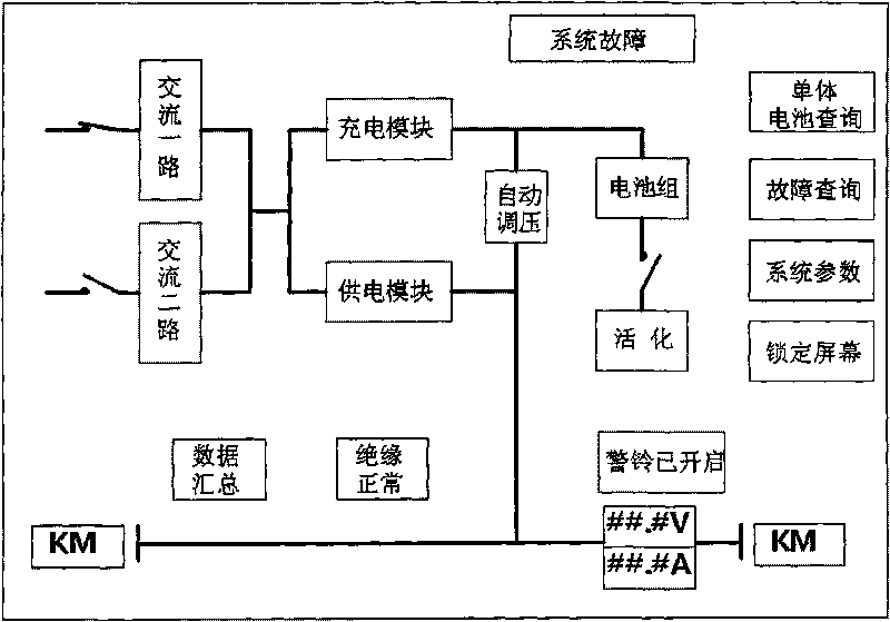
[0029] When the device 1 in the AC panel (such as a lightning arrester) fails, its fault data or switching value is collected by the AC monitoring unit. After the CPU in the AC monitoring unit judges that the data or switching value is a fault phenomenon, it will send the fault data through the RS232 / 485 communication interface. The data is uploaded to the programmable logic controller PLC. After analyzing the data, the PLC judges the location of the device 1 that caused the fault, controls the fault buzzer to sound an alarm, and uploads the data to the touch screen display through the RS232 / 485 interface at the same time: first Display "System Fault" on the main screen, such as Figure 4 , and secondly, display the specific fault content on the fault query screen in the form of lighting up the optical name plate (such as Figure 5 ), and at the same time query the screen at the fault location (such as Image 6 ) shows that the screen where the faulty device is located is an ...
Embodiment 2
[0031] When the device 2 (such as the inverter module) in the emergency lighting panel fails, its fault data or switching value is collected by the module monitoring unit. After the CPU in the module monitoring unit judges that the data or switching value is a fault phenomenon, it communicates through RS232 / 485 The interface uploads the fault data to the programmable controller PLC. After analyzing the data, the PLC judges the location of the device 2 that caused the fault, controls the fault buzzer to sound an alarm, and uploads the data to the touch screen through the RS232 / 485 interface at the same time Display: first display "system failure" on the main screen, (such as Figure 4 ), followed by displaying the specific fault content on the fault query screen in the form of light-on boards (such as Figure 5 ), and at the same time query the screen at the fault location (such as Image 6 ) shows that the screen where the fault device is located is the accident lighting scre...
Embodiment 3
[0033]When the device 3 in the DC panel (such as DC monitoring communication) fails, its fault data or switching value is collected by the DC monitoring unit. After the CPU in the DC monitoring unit judges that the data or switching value is a fault phenomenon, it can communicate through the RS232 / 485 communication interface. Upload the fault data to the programmable logic controller PLC. After analyzing the data, the PLC judges the location of the device 3 that caused the fault, controls the fault buzzer to sound an alarm, and uploads the data to the touch screen display through the RS232 / 485 interface at the same time : Firstly, "system failure" will be displayed on the main screen, (such as Figure 4 ), followed by displaying the specific fault content on the fault query screen in the form of light-on boards (such as Figure 5 ), and at the same time query the screen at the fault location (such as Image 6 ) shows that the screen where the faulty device is located is a DC ...
PUM
 Abstract
Description
Claims
Application Information
 - R&D Engineer
- R&D Manager
- IP Professional
- Industry Leading Data Capabilities
- Powerful AI technology
- Patent DNA Extraction
Browse by: Latest US Patents, China's latest patents, Technical Efficacy Thesaurus, Application Domain, Technology Topic, Popular Technical Reports.
© 2024 PatSnap. All rights reserved.Legal|Privacy policy|Modern Slavery Act Transparency Statement|Sitemap|About US| Contact US: help@patsnap.com