Short magnetic circuit reluctance motor, and double stator magnetic poles, rotor core and wound rotor

A reluctance motor, stator pole technology, applied in the direction of magnetic circuit rotating parts, magnetic circuit shape/style/structure, magnetic circuit stationary parts, etc., can solve the problem of hindering reluctance motor conversion efficiency, unseen, end Winding magnetic field energy is not well utilized and other issues

Inactive Publication Date: 2010-06-16
张玉宝
View PDF2 Cites 10 Cited by
  • Summary
  • Abstract
  • Description
  • Claims
  • Application Information

AI Technical Summary

Problems solved by technology

Undoubtedly, the magnetic field energy of the end winding, which accounts for a considerable proportion of the circumference of the excitation winding, has not been well utilized, which also hinders the further improvement of the conversion efficiency of the reluctance motor in the prior art
[0019] (3) In the prior art, the inner rotor core with more than three salient poles, the outer rotor core with three salient poles and the outer rotor core with more tha...

Method used


Image

  • Short magnetic circuit reluctance motor, and double stator magnetic poles, rotor core and wound rotor
  • Short magnetic circuit reluctance motor, and double stator magnetic poles, rotor core and wound rotor
  • Short magnetic circuit reluctance motor, and double stator magnetic poles, rotor core and wound rotor

Examples


Embodiment Construction

[0076] The present invention will be described in further detail below with specific embodiments in conjunction with the accompanying drawings.

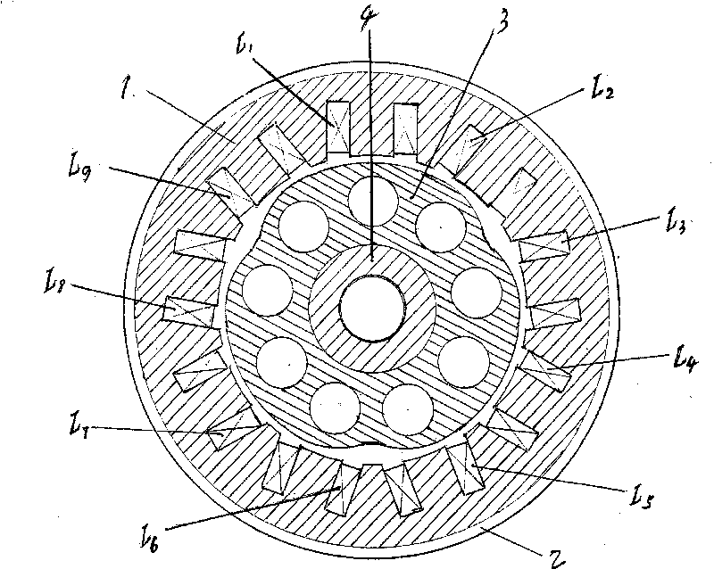
[0077] according to figure 1 As shown, the present invention is composed of (single-slot) three-section compound stator poles and a radial-phase-splitting inner rotor three-phase 9 / 3-pole short magnetic circuit reluctance motor composed of a three-salient pole multi-arc boss rotor. It is a (single slot) compound stator pole L that is arranged radially and equidistantly distributed on the circumference of the continuous stator core 1. 1 L 2 L 3 L 4 L 5 L 6 L 7 L 8 L 9 The main and auxiliary magnetic poles are divided into three sections along the axial direction. The middle section is as long as the main magnetic pole, and is made of silicon steel sheets in the axial direction, and the two ends of the two sides are made of soft iron. Finally, they are combined by connecting technology to form a complete annular groove with - ...


PUM


Abstract

The invention discloses a short magnetic circuit reluctance motor, and double stator magnetic poles, a rotor core and a wound rotor. The three-phase 9/3 pole short magnetic circuit reluctance motor divides nine groups of double stator magnetic poles distributed on the circumference of a stator (1) at equal intervals into three sections in axial direction, wherein the length of the middle section is equal to that of a main magnetic pole and the middle section is manufactured by overlapping silicon-steel sheets; other main and auxiliary magnetic poles are manufactured into appropriate shapes by soft iron so that the three sections of main and auxiliary magnetic poles can be formed into the double stator magnetic pole with an annular groove for placing exciting windings after being combined together; then, the nine exciting windings (L1, L2, L3, L4, L5, L6, L7, L8 and L) are respectively arranged in each annular groove to obtain three-phase exciting windings (L1, L4, L7 and L2, L5, L8 and L3, L6, L9) on the circumference of the stator (1) in turn according to the rule of equilateral triangles; and then, a three-salient pole rotor core (3) consisting of a multi-cambered surface lug boss is arranged on a hollow rotor shaft lever (4) with internal thread and forms rotating connection with a stator part through a periphery connecting and fixing device of a motor.

Description

Technical field: [0001] The invention relates to a compound stator magnetic pole used in a reluctance motor and a short magnetic circuit reluctance motor adopting a compound stator magnetic pole. Reluctance motors, axially split-phase short-circuit reluctance motors using compound stator poles, radial-phase split-type reciprocating short-circuit reluctance motors using compound stator poles, and linear reciprocating short-circuit reluctance motors using compound stator poles Magnetic circuit reluctance motor. The present invention also relates to the rotor (moving) sub-core used in the short-circuit reluctance motor adopting the compound stator magnetic poles, which includes the rotor (moving) sub-core composed of a plurality of bosses with bidirectional guiding parts and a plurality of The invention also relates to a rotor with windings for a short magnetic circuit reluctance motor. Background technique: [0002] The reluctance motors in the prior art all adopt a double s...

Claims


Application Information

Patent Timeline
IPC IPC(8): H02K1/12H02K1/24H02K3/12H02K3/28H02K29/00
Inventor 张玉宝
Owner 张玉宝
Why Eureka
Try Eureka