Brushless electronic water pump

An electronic water pump and stator assembly technology, applied in the direction of pumps, pump devices, pump components, etc., can solve the problems of poor heat dissipation effect, shortened service life, and small water output of electronic water pumps, so as to avoid rust or lubrication failure, use Long life and low rotational resistance

Pending Publication Date: 2017-05-10
JIANGSU LANGXIN ELECTRIC
View PDF6 Cites 4 Cited by
  • Summary
  • Abstract
  • Description
  • Claims
  • Application Information

AI Technical Summary

Problems solved by technology

This structure is actually a simple superposition of two types of motor and water pump, which has high cost, large volume and low conversion efficiency.
[0003] An electronic water pump with a patent number of ZL 201410425454.3 discloses a water pump with another structure, including an outer shell, an isolation sleeve, a stator component, and a rotor component. The isolation sleeve separates the space in the electronic water pump into an accommodation cavity and a fluid cavity, and the rotor Components include rotor core, blade injection molded body, rotating shaft, and the upper and lower ends of the rotating shaft of the rotor parts need to be rotated and installed on the first bearing and the second bearing, and the first bearing is installed on the supporting seat, and the supporting seat is installed on the bracket , this installation method has the following disadvantages: 1. The support base and the bracket are set up, thus occupying the water inlet space and reducing the water intake; 2. The first bearing is set on the support base, and the surrounding of the support base is always flowing Although the liquid can be isolated by sealing fit, since the rotor assembly is always rotating, the sealing reliability is very low, and the first bearing may always be soaked in water, and the first bearing is prone to rust over time, so the first bearing If the rotation is not smooth, the rotation resistance of the rotor assembly will increase, the efficiency will become lower and lower, and even the electronic water pump will be damaged due to excessive wear.
3. The rotor parts rotate at high speed, which will have a certain impact on the support seat and bracket, especially when installed on a car, the electronic water pump is always in a bumpy environment, so the support seat and bracket are required to be more firm, and the bracket The support seat is generally made of plastic material, and it needs to be convenient for liquid to flow through. Therefore, its installation position and structure itself limit its structure. Low performance and shortened service life; 4. The blade injection molded body of this patent is an open structure, that is, the blade of the blade injection molded body is in the first housing, and the liquid enters the first housing and is exported from the outlet by the rotating blade fluctuations. Low water pressure and small water output
5. The heat dissipation effect of this electronic water pump is very poor. Since the PCB board is installed in the second casing and only relies on a heat dissipation aluminum plate for heat dissipation, and the exported heat is still in the second casing, the temperature of the electronic water pump is high during operation, which affects Normal work of the PCB board

Method used


Image

  • Brushless electronic water pump
  • Brushless electronic water pump
  • Brushless electronic water pump

Examples


Embodiment Construction

[0039] The present invention will be described in further detail below through specific examples.

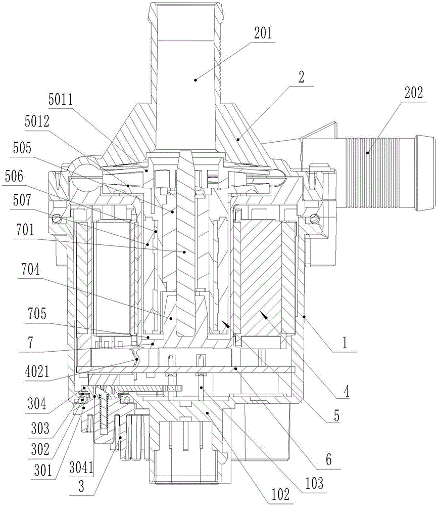
[0040] The up and down orientation in this embodiment is to place the electronic water pump according to figure 2 The placement position is determined.

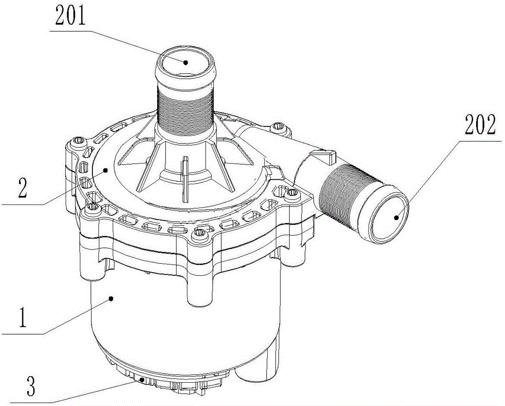
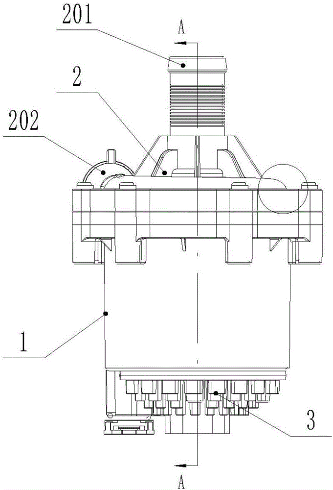
[0041] Such as Figure 1 to Figure 12 As shown, a brushless electronic water pump includes a detachable and fixed outer shell 1, a spacer 7 and an upper cover 2. The outer shell 1 is cylindrical, and the bottom of the outer shell 1 is provided with a through hole for installation. The cooling device 3 is installed, and the bottom of the outer casing 1 is also provided with a waterproof and breathable valve 101, which is used to increase the breathable effect and realize the waterproof effect at the same time. The upper cover 2 is provided with a water inlet 201 and a water outlet 202 , the upper cover 2 and the spacer 7 are sealed by an upper sealing ring 8 , and the spacer 7 and the outer shell 1 are also sealed. Screws ar...


PUM


Abstract

The invention discloses a brushless electronic water pump. The brushless electronic water pump comprises a shell body, an isolating sleeve and an upper cover which can be detachably fixed. The isolating sleeve divides the shell body and the upper cover into an installing chamber and a fluid chamber. A stator assembly and a PCB are fixed into the installing chamber. A rotor assembly is installed in the fluid chamber in a rotating manner. The upper cover is provided with a water inlet and a water outlet. The rotor assembly comprises an impeller and a connecting drum. A wear-resisting lubricating insert is fixedly inserted into an inner hole of the connecting drum. A center hole is formed in the wear-resisting lubricating insert. A magnet yoke drum is fixedly installed outside the connecting drum concentrically in a sleeving manner. A magnet ring drum is fixedly installed outside the magnet yoke drum concentrically in a sleeving manner. The isolating sleeve is provided with a locating center shaft which is inserted into the center hole. The shell body is provided with a heat dissipating device connected with the PCB in a heat-conducting manner. According to the brushless electronic water pump, a bearing does not need to be arranged on a rotor, no water inlet space is occupied, the reliability of the brushless electronic water pump is improved, and the service life of the brushless electronic water pump is prolonged.

Description

technical field [0001] The invention relates to an electronic water pump, in particular to a brushless electronic water pump. Background technique [0002] The current electronic water pump includes a motor stator and a motor rotor, the rotor shaft is connected to the outer magnetic steel of the water pump, the inner magnetic steel of the water pump is placed in the outer magnetic steel, and the impeller is connected to the inner magnetic steel. The electronic rotor cooperates, and the external magnetic steel and the internal magnetic steel cooperate to complete the drive rotation of the impeller. This structure is actually a simple superposition of two types of motor and water pump, which has high cost, large volume and low conversion efficiency. [0003] An electronic water pump with a patent number of ZL 201410425454.3 discloses a water pump with another structure, including an outer shell, an isolation sleeve, a stator component, and a rotor component. The isolation sle...

Claims


Application Information

Patent Timeline
Patent Type & Authority Applications(China)
IPC IPC(8): F04D13/06F04D29/22F04D29/58F04D29/06F04D29/02H02K7/14
CPCH02K7/14F04D13/06F04D29/026F04D29/061F04D29/2222F04D29/586
Inventor 丁言闯戚纯波刘宇鹏
Owner JIANGSU LANGXIN ELECTRIC
Why Eureka
Try Eureka