Automatic feeding device for die punching

An automatic feeding and punching technology, applied in the direction of feeding device, positioning device, storage device, etc., can solve the problems of unsafe manual operation, low processing precision, slow processing speed, etc., achieve labor intensity reduction, reasonable structural design, The effect of improving work efficiency

Active Publication Date: 2010-06-23
鞍钢房地产开发集团有限公司
View PDF0 Cites 15 Cited by
  • Summary
  • Abstract
  • Description
  • Claims
  • Application Information

AI Technical Summary

Problems solved by technology

[0002] In the punching process of steel pipe mold, it is generally completed by the way of upper and lower molds plus mandrel. This kind of mold is manually shifted on the punching machine, and the punching machine worker uses the foot to st

Method used


Image

  • Automatic feeding device for die punching
  • Automatic feeding device for die punching
  • Automatic feeding device for die punching

Examples


Embodiment Construction

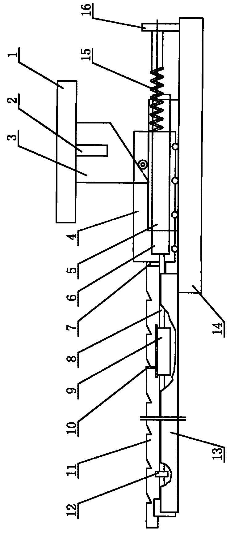
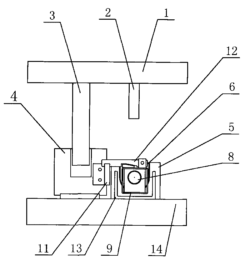
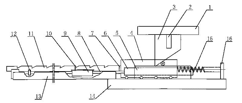
[0009] An automatic feeding device for die punching, such as figure 1 , figure 2 As shown, it includes an upper mold base 1 and a lower mold base 14, the upper and lower molds are fixed on the punching machine, and the upper mold base 1 is fixed with punching and shearing blades 2 and inclined irons 3; the middle part of the lower mold base 14 is fixed with a lower die 5, and the front An extension plate 13 is fixed, and a fixed plate 16 is installed at the rear; the fixed plate 16 is provided with a spring 15, and the front end of the spring 15 is connected with a slider 4, and the front end of the slider 4 is provided with a baffle plate 7 and a rack plate 11; The front end is fixed on the extension plate 13, the mandrel 6 is fixedly installed on the rear end, and the front end of the support rod 8 is fixed with a scale plate 12; Rod 10 head is stuck in the tooth groove of rack plate 11.

[0010] When the steel pipe is punched, the device of the present invention is insta...


PUM


Abstract

The present invention relates to an automatic feeding device for die punching, comprising an upper die holder and a lower die holder. Punching shear blades and an iron wedge are fixed on the upper die holder. A lower die is fixed in the middle of the lower die holder, an extending plate is fixed on the front part, and a fixing plate is arranged on the rear. A spring is arranged on the fixing plate, a slider is connected to the front end of the spring, and a baffle and a rack plate are arranged at the front end of the slider. The front end of a support rod is fixed on the extending plate, the rear end is fixedly provided with a core die, and a sizing plate is fixed at the front end of the support rod. A propeller is sheathed on the support rod, a motor lock rod is arranged on the propeller, and the head of the motor lock rod is clamped in the tooth socket of the rack plate. The device of reasonable structure design can be mounted on a punch for punching steel pipes. The efficiency is high, and the work intensity of operators is largely reduced.

Description

technical field [0001] The invention relates to a steel pipe processing tool, in particular to an automatic feeding device for die punching. Background technique [0002] In the punching process of steel pipe mold, it is generally completed by the way of upper and lower molds plus mandrel. This kind of mold is manually shifted on the punching machine, and the punching machine worker uses the foot to step on the pedal and move once every time to complete the punching and shearing of a hole. , the traditional method has the following problems; 1. The processing speed is slow; 2. The processing accuracy is low; 3. Manual operation is unsafe; Contents of the invention [0003] The invention overcomes the deficiencies in the prior art and provides an automatic feeding device for die punching with reasonable structural design, convenient operation and high working efficiency. [0004] In order to solve the above problems, the present invention adopts the following technical sol...

Claims


Application Information

Patent Timeline
IPC IPC(8): B21D43/04B21D28/34B21D37/12B21D28/28
Inventor 关文满刘娜
Owner 鞍钢房地产开发集团有限公司
Why Eureka
Try Eureka