Device for melt-spinning and winding multiple synthetic threads

A filament and equipment technology, applied in the field of equipment for melt spinning and winding a large number of synthetic filaments

Active Publication Date: 2010-06-23
OERLIKON TEXTILE GMBH & CO KG
View PDF6 Cites 12 Cited by
  • Summary
  • Abstract
  • Description
  • Claims
  • Application Information

AI Technical Summary

Problems solved by technology

However, such a cooling device has the disadvantage that the individual filaments of the filaments are only blown on one side with a stream of cooling air.

Method used


Image

  • Device for melt-spinning and winding multiple synthetic threads
  • Device for melt-spinning and winding multiple synthetic threads
  • Device for melt-spinning and winding multiple synthetic threads

Examples


Embodiment Construction

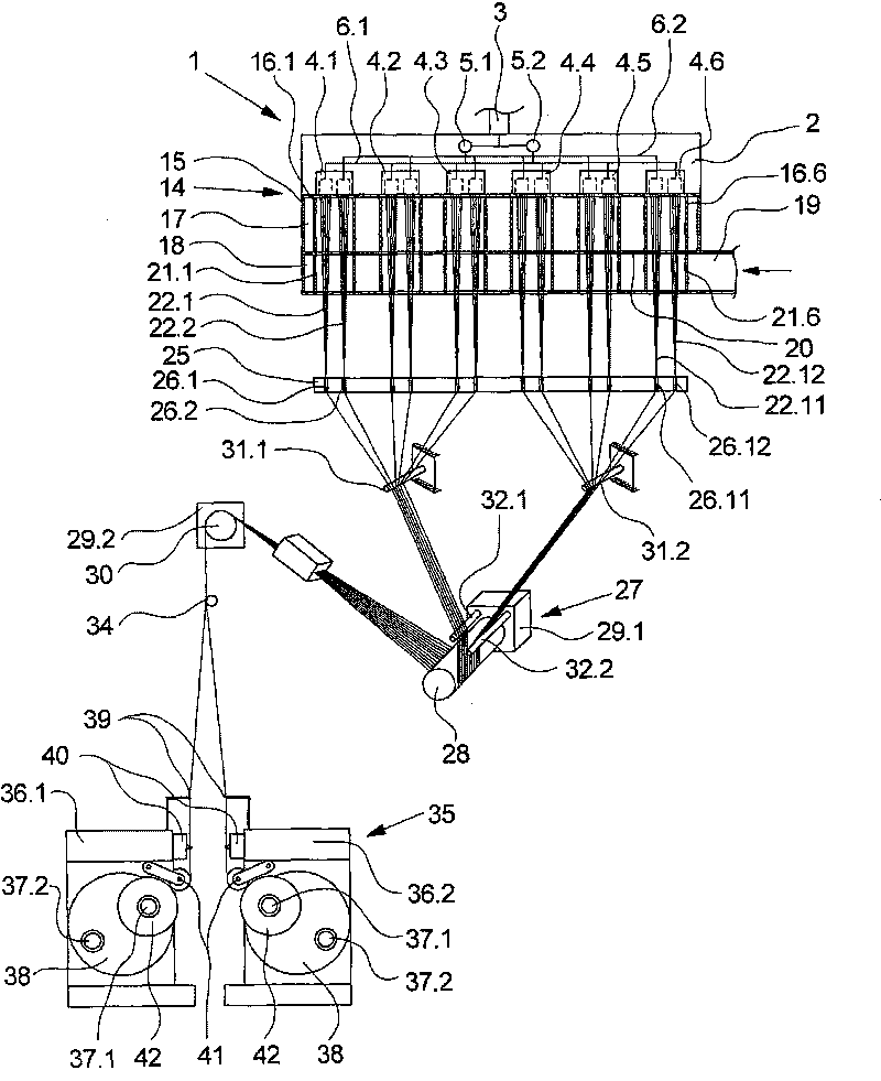
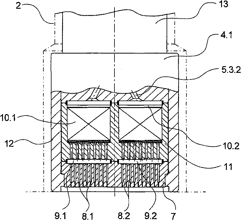
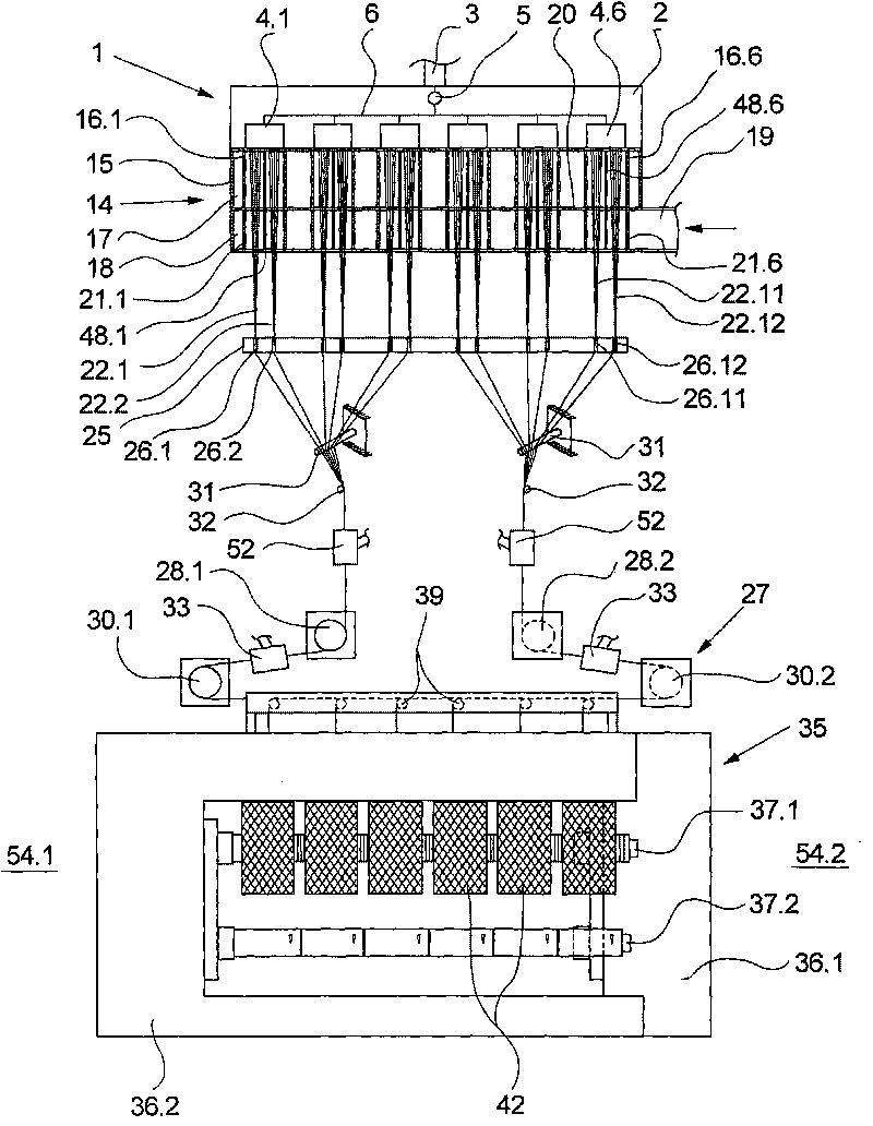
[0028] figure 1 A first embodiment of an apparatus for melt spinning and winding large quantities of synthetic filaments according to the invention is schematically shown in . For the production of the filaments, the system has a spinning device 1 , a cooling device 14 connected downstream of the spinning device 1 , a drawing device 27 and a downstream winding device 35 for winding up the filaments. The spinning device 1 has a plurality of spinning nozzle assemblies 4.1 to 4.6 arranged parallel to one another. The spin nozzle assemblies 4.1 to 4.6 are held on a lower side of a heatable spin beam 2 . The spinning beam 2 comprises two spinning pumps 5.1 and 5.2, which are connected to the respective spinning nozzle assemblies 4.1 to 4.6 via a distribution line 6.1 and 6.2 respectively. The spinning pumps 5.1 and 5.2 are connected via a melt inlet 3 to a melt source not shown here in greater detail, for example an extruder. The individual spinning pumps 5.1 and 5.2 are designe...


PUM


Abstract

The present invention relates to a device for multi-spinning and winding multiple synthetic threads. Thus a plurality of spinning nozzle assemblies are kept to a lower surface of a spinning box and are connected with a melt source. A cooling device used for cooling thread is provided behind the spinning box, wherein, the cooling device is provided with a blow case connected with a cooling air generator. The blow case is provided with a plurality of cooling cylinders which are configured concentrically with each spinning nozzle assembly and are provided with ventilated cylinder walls, wherein, each cooling cylinder passes through the blow case with distance from one another. At least one drawing device used for drawing threads and a winding device used for winding each thread to a roll are provided below the cooling device. For spinning and cooling the threads in a compact structure as possible, according to the invention, each spinning nozzle assembly is configured so that each spinning nozzle assembly can squeeze out at least two threads and furthermore each cooling cylinder can cool at least two threads.

Description

technical field [0001] The invention relates to an apparatus for melt-spinning and winding large quantities of synthetic filaments according to the preamble of claim 1 . Background technique [0002] A device of this type for melt spinning and winding large quantities of synthetic filaments is known, for example, from US 2002 / 0114857 A1. [0003] In known devices, a plurality of spinning nozzle assemblies are arranged side by side on a lower surface of a spinning beam, so that each spinning nozzle extrudes a filament. The individual filaments forming the filament are cooled after extrusion by means of cooling air. For this purpose, a blow box is arranged below the spinning beam, which has a concentrically arranged cooling cylinder per spinning nozzle assembly, which surrounds the individual filaments of the filament. The cooling cylinder has a gas-permeable cylinder wall so that the individual filaments of the filament can be cooled evenly from all sides. Each individual ...

Claims


Application Information

Patent Timeline
Patent Type & Authority Applications(China)
IPC IPC(8): D01D4/00D01D4/02D01D4/06D01D5/092D01D5/096D01D11/00D01D13/02
CPCD01D5/092D01D13/00D01D4/00
Inventor M·赖希魏因U·恩德斯R·尼奇克S·P·辛格
Owner OERLIKON TEXTILE GMBH & CO KG
Why Eureka
Try Eureka