Energy-saving oil pumping mechanism used for oil field

An oil pumping mechanism and oil field technology, applied in the fields of production fluids, wellbore/well components, earthwork drilling, etc., can solve problems such as the impact of oil production efficiency, low transmission efficiency, impact on the service life of motors and gearboxes, and achieve the integration of electromechanical The effect of high degree of chemicalization, safe and reliable use, and concise overall structure

Inactive Publication Date: 2010-06-23
张墅
View PDF8 Cites 7 Cited by
  • Summary
  • Abstract
  • Description
  • Claims
  • Application Information

AI Technical Summary

Problems solved by technology

However, this patented technical solution has the following shortcomings: one is that the gear and rack are meshed, so the transmission resistance is large, resulting in low transmission efficiency; the other is that the reverse impact is large, which may damage the gear and rack. It is easy to cause tooth collapse; the third is to provide guide rail lubricating oil pool for the lubrication of the rack and pinion (the third line from the bottom on the second page of the manual and the image 3 shown), thus causing troubles to use, such as the need to regularly or irregularly replenish oil to the lubricating oil pool of the guide rail, once the lubricating oil pool of the guide rail is less oily or even cut off, it will easily cause damage to the gear rack or cause running resistance increase (big friction); Fourth, whenever a stroke of up and down reciprocating motion is completed, the motor and the reduction box move up and down once through the meshing of the four gears mounted on the reduction box and the rack track (instructions No. 3 Page 3 to 7 lines), so not only the energy consumption of motion is large, which is not enough to reflect the ideal energy-saving effect, but also affects the service life of the motor and gearbox that are always in the up and down motion state; fifth, it cannot reflect the dual-use of one machine , that is, two wells and one machine cannot be alternately pumped at the two wellheads at the same time, so the oil recovery efficiency is affected, especially the number of units put into use in the oilfield is increased (one well and one machine); the sixth is that the overall structure is complex, the manufacturing cost is large and it is in the The workload and difficulty of management and maintenance are large during use

Method used


Image

  • Energy-saving oil pumping mechanism used for oil field
  • Energy-saving oil pumping mechanism used for oil field
  • Energy-saving oil pumping mechanism used for oil field

Examples


Embodiment Construction

[0022] In order to enable the examiners of the patent office, especially the public, to understand the technical essence and beneficial effects of the present invention more clearly, the applicant will describe in detail below in conjunction with the accompanying drawings in the form of embodiments, but none of the descriptions of the embodiments is a description of the present invention. Restriction of the inventive solution, any equivalent transformation made according to the concept of the present invention which is only in form but not in substance shall be regarded as the scope of the technical solution of the present invention.

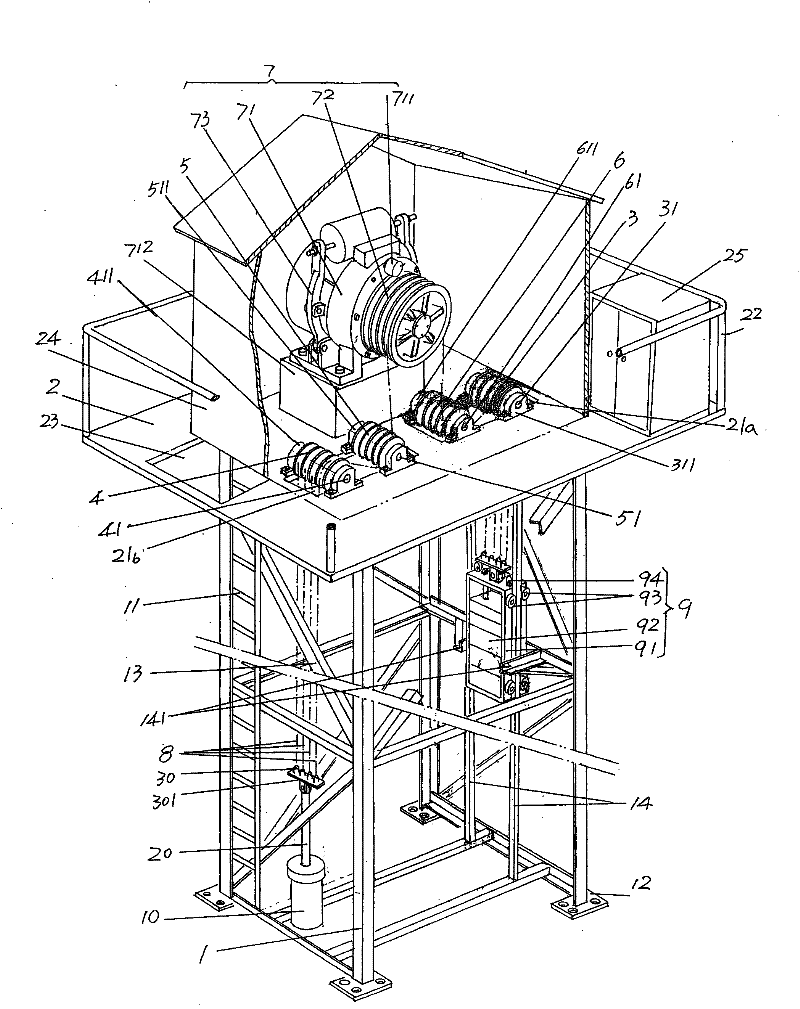
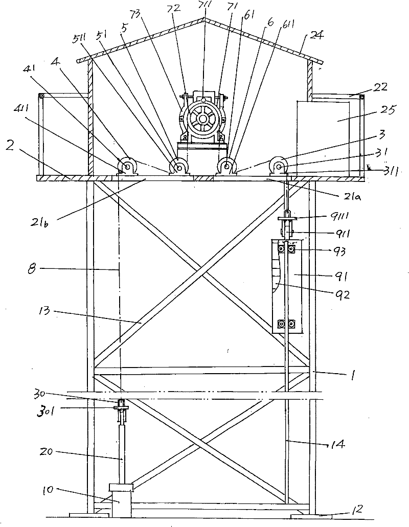
[0023] please see figure 1 and figure 2 , shows the derrick 1 whose height, size and structural form are not limited by the diagram but preferably appears in the form of a well-shaped frame. In order to make the derrick 1 stable, it is reinforced with diagonal braces 13. When it is put into use in the oil field, That is, in the state of use, ...


PUM


Abstract

The invention discloses an energy-saving oil pumping mechanism used for oil field, which belongs to the technical field of oil exploitation machinery and includes a derrick, a machine platform, a first head block assembly and a second head block assembly, a first transition block assembly, and a second transition block assembly, a power device, and a hauling cable. The machine platform is provided with a first hauling cable hole and a second hauling cable hole on a platform surface and is provided with barriers on the surrounding of the platform surface; and the machine platform is fixed on the top of the derrick. The first head block assembly and the second head block assembly are fixed on the machine platform; the first transition block assembly and the second transition block assembly are arranged on the machine platform; the power device consists of a tractor, a traction sheave and a brake, and is arranged on the machine platform; one end of the hauling cable is connected with a sucker rod and the other end is twisted on the second head block assembly, the first transition block assembly, the traction sheave, the second transition block assembly and the first head block assembly, and then is induced into the first hauling cable hole and is connected with the sucker rod of another oil well pipe or is connected with a counterweight device. The energy-saving oil pumping mechanism used for oil field has a high transmission efficiency, is convenient, safe and convenient to be used, has a simple integral structure, is convenient to be managed and protected, can realize to configure two wells for one machine, has high mechatronics degree and saves power energy.

Description

technical field [0001] The invention belongs to the technical field of petroleum exploitation machinery, and in particular relates to an energy-saving oil pumping mechanism for oilfields. Background technique [0002] The technical schemes of pumping units used in oil fields can be found in a large number of Chinese patent documents. The utility model patent authorization announcement number CN2528932Y recommends a linkage variable torque beam pumping unit; the authorization announcement number CN2553108Y provides a dovetail beam Oil pumping unit; Publication number CN101148978A introduces a kind of curved pull type pumping unit; Publication number CN101161985A recommends a kind of energy-saving beam pumping unit; Publication number CN101182762A discloses a kind of beam-type energy-saving pumping unit; Publication number CN101215961A discloses an energy-saving pumping unit with a T-shaped beam structure; the authorized announcement number CN201354627Y discloses a beam pumpin...

Claims


Application Information

Patent Timeline
Patent Type & Authority Applications(China)
IPC IPC(8): E21B43/00
Inventor 张墅张重
Owner 张墅
Why Eureka
Try Eureka