Mechanical sealing structure of pearl-row-like annular groove zoning end face

A kind of end face mechanical seal and mechanical seal technology, applied in the direction of engine seal, mechanical equipment, engine components, etc., can solve the problems of complex structure, large leakage, etc., achieve wide application range, improve dynamic pressure effect, and improve wear resistance Effect

Inactive Publication Date: 2010-06-23
JIANGSU HUAHAI STEEL STRUCTURE CO LTD
View PDF3 Cites 19 Cited by
  • Summary
  • Abstract
  • Description
  • Claims
  • Application Information

AI Technical Summary

Problems solved by technology

[0003] In order to improve the pressure resistance, wear resistance and stability of the mechanical seal under high-speed and heavy-load conditions, thereby prolonging the service life, and overcoming the problems of large l

Method used


Image

  • Mechanical sealing structure of pearl-row-like annular groove zoning end face
  • Mechanical sealing structure of pearl-row-like annular groove zoning end face
  • Mechanical sealing structure of pearl-row-like annular groove zoning end face

Examples


Embodiment 1

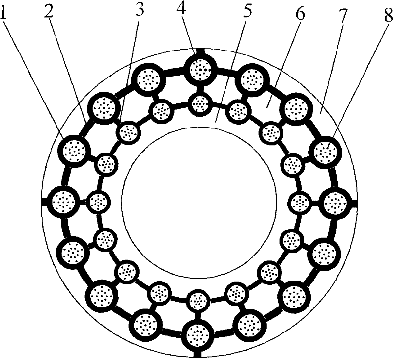
[0030] refer to figure 1 , like a pearl chain-shaped circular ring groove ring with an end-face mechanical seal structure, including a rotating ring and a static ring of a mechanical seal, at least one of the sealing rings in the rotating ring and the static ring is provided with holes symmetrical to the center of rotation. A pearl-chain-like annular band composed of several circular grooves, each circular groove 1 surrounds a circular boss 4, and annular sealing dams 5, 7 are provided on the inside and outside of the sealing end surface ; The annular grooves 1 on the same ring belt are communicated through the circumferential arc grooves 2 .

[0031] There are two or more annular bands, and the radii of the annular grooves 1 on different annular bands gradually decrease along the leakage direction of the sealing medium.

[0032] The radially adjacent annular grooves 1 on different annular belts communicate with each other through connecting grooves 3 . The connection groove...

Embodiment 2

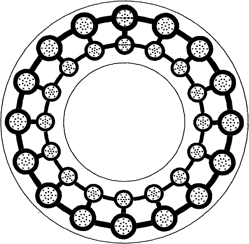
[0038] refer to figure 2 , image 3 The difference between this embodiment and the first embodiment is that the annular groove 1 on the outer ring belt is not connected to the high-pressure side of the sealing medium, which is suitable for low viscosity sealing medium; other structures and functions are the same as the first embodiment.

Embodiment 3

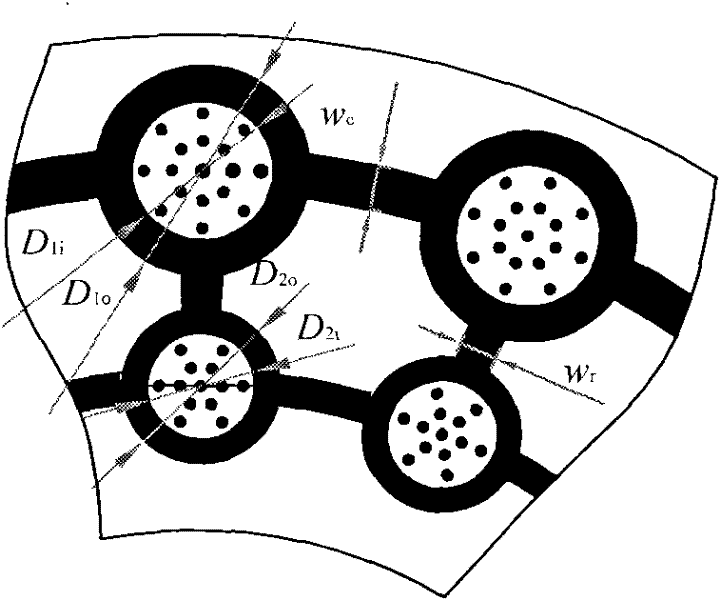
[0040] refer to Figure 4 The difference between this embodiment and the second embodiment is that the surface 6 of the boss area between the adjacent ring grooves is provided with micropores. This structure further improves the uniformity of pressure distribution of the end film, improves the opening force of the end face, and further absorbs fine particles in the medium. When the seal is only required to have excellent low-speed and low-pressure start-up performance, it can only communicate with the annular groove 1 on the same radius circle, see Figure 5 ; When the sealed medium is gas, it is only necessary to communicate with the circular groove 1 in the circumferential direction, and when the sealed medium is liquid, the effect of connecting the circular groove 1 in the radial direction will be better. Other structures and functions are the same as those in Embodiment 2.


PUM


Abstract

The invention relates to a mechanical sealing structure of a pearl-row-like annular groove zoning end face, comprising mechanically sealed rotating rings and static rings. The end face of at least one of the sealed rotating rings and the static rings is provided with pearl-row-like annular zones, and the pearl-row-like annular zones are composed of a plurality of annular grooves, and are distributed symmetrically to a rotating center, each annular groove is arranged round a circular convex table, annular sealing dams are arranged inside and outside the end face, and the annular grooves on thesame annular zones are communicated through circumferential arc grooves. The mechanical sealing structure of the pearl-row-like annular groove zoning end face has the advantages of good wearing resistance, low-speed low-pressure starting and dynamic pressure, and can be applied to seal common liquid and gases.

Description

technical field [0001] The invention relates to a pearl chain-like annular groove ring belt end face mechanical seal structure, which belongs to the end face sealing device of a rotating shaft, and is suitable for the shaft end sealing device for rotating shafts of various compressors, pumps, kettles and other rotating equipment. Background technique [0002] The shaft seals of rotating mechanical equipment mainly use mechanical seals, packing seals, oil seals and labyrinth seals. In 1885, the first mechanical seal patent appeared in the UK. In the early 1960s, China firstly used mechanical seals in Lanzhou Oil Refinery, and later developed mechanical seals by itself. Now it has been widely used in industries such as petroleum, chemical industry, metallurgy, machinery, aviation and atomic energy. In mechanical seals, the heat generated by friction and stirring will increase the temperature of the sealing ring, especially the sealing end surface, especially for heavy-duty oc...

Claims


Application Information

Patent Timeline
IPC IPC(8): F16J15/34
Inventor 彭旭东刘鑫李纪云孟祥铠
Owner JIANGSU HUAHAI STEEL STRUCTURE CO LTD
Why Eureka
Try Eureka