
Embedded burner

A burner, embedded technology, applied in burners, gas fuel burners, combustion methods, etc., can solve problems such as excessive gas, reactive power loss, unreasonable matching, etc., and achieve the effect of reducing emissions and improving gas efficiency

Inactive Publication Date: 2010-06-23
佛山市顺德区澳羚究星电子科技有限公司
View PDF9 Cites 2 Cited by
  • Summary
  • Abstract
  • Description
  • Claims
  • Application Information

AI Technical Summary

Problems solved by technology

[0002] At present, in the gas appliance industry, especially the civil gas industry, with the intensification of market competition, various manufacturers continue to develop stoves with multiple functions and a wide range of applications on the basis of the original design. In the overall design, the basic focus is on how to improve thermal efficiency. The core is to solve the problem of the mixing ratio of gas and air in the gas preparation, specifically related to the swirl burner. The main problem of existing products is that the design of the flame hole is usually a straight line. Or arc, compared with ordinary needle-shaped fire holes, the gas burned per unit time is obviously more, but due to the unreasonable matching between the current gas supply and mixed air, it is easy to cause carbon monoxide, an important indicator. Exceeding the standard and reactive power loss of gas, with the popularization of embedded combustion appliances, this situation is becoming more and more prominent

Method used


Image

  • Embedded burner
  • Embedded burner
  • Embedded burner

Examples


Embodiment Construction

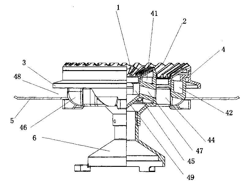
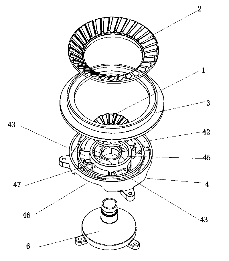
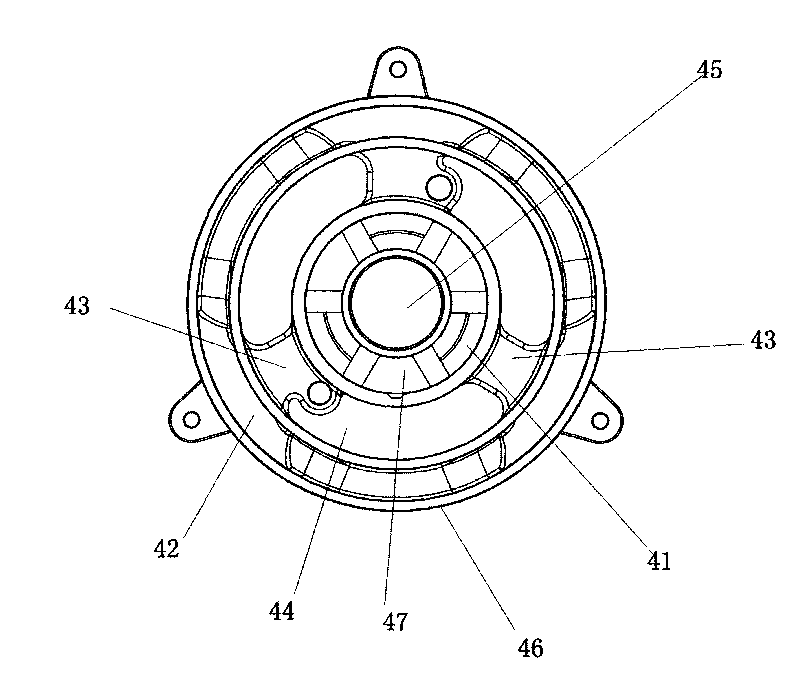
[0013] The present invention as figure 1 , figure 2 , image 3 As shown, an embedded burner includes an inner fire cover 1, an outer fire cover 2, a cover ring 3, a gas seat 4, a water tray 5 and an air mixing pipe 6 with a swirl structure, and the gas seat 4 is provided with a positive To inner and outer fire cover 1, the inner ring gas groove 41, the outer ring gas groove 42 of 2, be provided with several gas passages 43 that make the two communicate between the inner and outer ring gas grooves 41 and 42, in each phase An open outer air mixing area 44 is provided between adjacent gas passages 43, an inner air mixing area 45 with a closed bottom is provided at the center of the gas seat 4, and an air mixing area 45 communicating with the outer air mixing area 44 is provided on the outer edge of the gas seat 4. The tuyere 46 is provided with an air mixing channel 47 between the outer air mixing area 44 and the inner air mixing area 45 , and an air guide groove 48 is reserve...


PUM


Abstract

The invention relates to an embedded burner. The burner comprises an inner burner cap, an outer burner cap, a cap ring, a gas seat, a water pond and a mixer pipe, wherein the gas seat is provided with an inner annular gas channel and an outer annular gas channel which are opposite to the inner burner cap and the outer burner cap, a plurality of gas passages for communicating the inner annular gas channel and the outer annular gas channel are arranged between the inner annular gas channel and the outer annular gas channel, an open outer mixer area is arranged between every two adjacent gas passages, the center of the gas seat is provided with an inner mixer area the bottom of which is sealed, the outer edge of the gas seat is provided with a mixer nozzle which is communicated with the outer mixer area, a mixer passage is arranged between the outer mixer area and the inner mixer area, and a wind guide groove is arranged between the cap ring and the water pond. By using the burner-surface horizontal mixer structure arranged on the embedded burner and composed of the inner mixer area and the outer mixer area of the mixer nozzle and the mixer passage and arranging the mixer passages from outside to inside along the horizontal direction of the burner, the invention ensures the more sufficient burning between the inner burner cap and the outer burner cap, improves the efficiency of the gas and can reduce the discharge amount of carbon monoxides to some extent, thereby achieving the effects of energy saving and environmental protection.

Description

technical field [0001] The invention relates to a gas appliance, in particular to an embedded burner. Background technique [0002] At present, in the gas appliance industry, especially the civil gas industry, with the intensification of market competition, various manufacturers continue to develop stoves with multiple functions and a wide range of applications on the basis of the original design. In the overall design, the basic focus is on how to improve thermal efficiency. The core is to solve the problem of the mixing ratio of gas and air in the gas preparation, specifically related to the swirl burner. The main problem of existing products is that the design of the flame hole is usually a straight line. Or arc, compared with ordinary needle-shaped fire holes, the gas burned per unit time is obviously more, but due to the unreasonable matching between the current gas supply and mixed air, it is easy to cause carbon monoxide, an important indicator. The excessive and rea...

Claims


Application Information

Patent Timeline
Patent Type & Authority Applications(China)
IPC IPC(8): F23D14/02F23D14/62
Inventor 胡志学
Owner 佛山市顺德区澳羚究星电子科技有限公司
Learn More