Soot blower structure of coal burning organic heating medium furnace

A heat carrier furnace and soot blower technology, which is applied to heat storage heaters, fluid heaters, combustion methods, etc., can solve the problems of short working life, large ash amount, and easy burnout of fixed soot blowers.

Inactive Publication Date: 2010-06-23
JIANGSU TAIHU BOILER
View PDF0 Cites 3 Cited by
  • Summary
  • Abstract
  • Description
  • Claims
  • Application Information

AI Technical Summary

Problems solved by technology

Therefore, the ash removal effect of the fixed soot blowing device installed at the tail is poor
However, if the fixed soot blower is installed at the junction of the high temperature convection section and the furnace, due

Method used


Image

  • Soot blower structure of coal burning organic heating medium furnace
  • Soot blower structure of coal burning organic heating medium furnace
  • Soot blower structure of coal burning organic heating medium furnace

Examples


Embodiment Construction

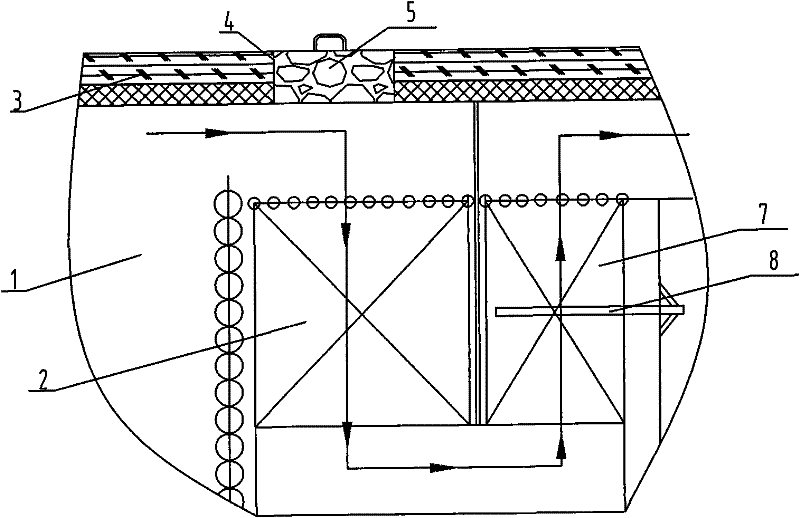
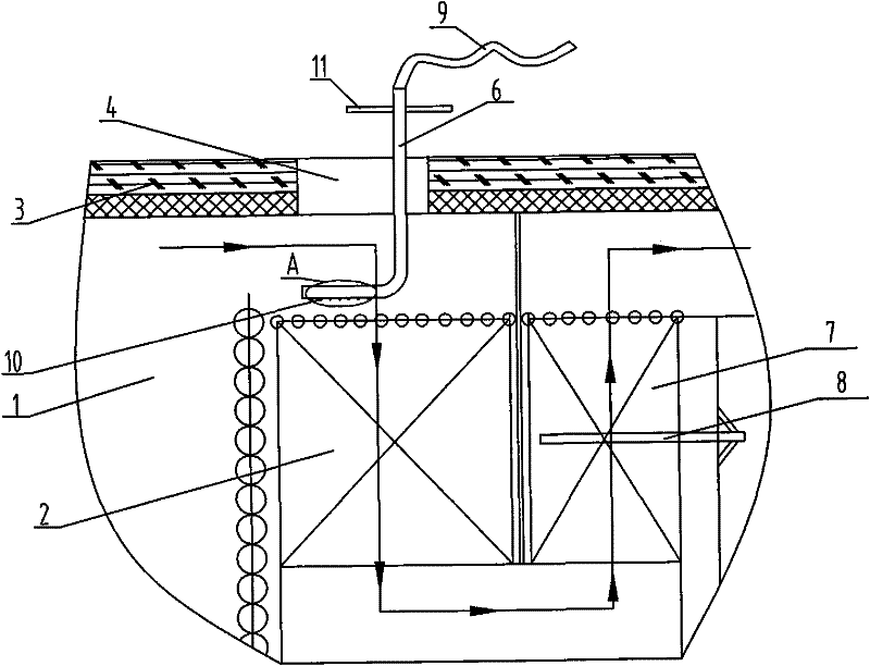
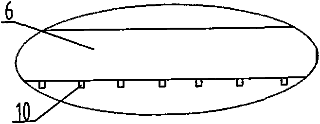
[0012] See figure 1 , figure 2 , image 3 , which includes a furnace 1, a high-temperature convection section 2, a furnace roof 3, a low-temperature convection section 7, and a fixed soot blower 8. The fixed soot blower 8 is installed in the low-temperature convection section 7, and the flue gas from the furnace 1 enters the space of the high-temperature convection section 2. Furnace top 3 has movable groove 4, movable groove 4 is nested with removable cover plate 5, and the junction of high temperature convection section 2 and furnace 1 is equipped with movable soot blowing device; the movable soot blowing device runs through and can be removed The movable groove 4 behind the cover plate 5, the soot blowing side of the movable soot blowing device is facing the junction of the high temperature convection section 2 and the furnace 1, and the intake side of the movable soot blowing device is connected to the external compressed air; the movable soot blowing device Specificall...


PUM


Abstract

The invention relates to a soot blower structure of a coal burning organic heating medium furnace. The soot blower structure has good soot removing effect and long working life and is beneficial to maintenance. The soot blower structure comprises a furnace hearth, a high-temperature convection section, a furnace top, a low-temperature convection section and a fixed soot blower. The fixed soot blower is arranged in the low-temperature convection section, soot in the furnace hearth enters an active groove which is open in the furnace top in the high-temperature convection section space, and the active groove is covered by and provided with a detachable cover plate. The soot blower structure is characterized in that the juncture of the high-temperature convection section and the furnace hearth is provided with an active soot blowing device.

Description

(1) Technical field [0001] The invention relates to the technical field of coal-fired organic heat carrier furnace equipment, in particular to a soot blower structure of a coal-fired organic heat carrier furnace. (2) Background technology [0002] The soot blower structure of the existing coal-fired organic heat carrier furnace is equipped with a fixed soot blower in the low-temperature convection section at the tail, because the ash deposits are all at the junction of the high-temperature convection section and the furnace. Therefore, the ash removal effect of the fixed soot blowing device installed at the tail is poor. However, if the fixed sootblower is installed at the junction of the high temperature convection section and the furnace, due to the high flue gas and large ash volume, the fixed sootblower is easy to burn out and has a short working life on the one hand, and on the other hand, it is often blocked Soot blowing holes are not conducive to maintenance. (3) C...

Claims


Application Information

Patent Timeline
IPC IPC(8): F24H7/00F23J1/00F23J3/00
Inventor 田忠权顾利平潘宇峰陶亚民张浩
Owner JIANGSU TAIHU BOILER
Why Eureka
Try Eureka