Compensated underwater brushless DC motor structure and assembly method thereof

A brushed DC motor and compensation type technology, applied in the field of compensation type underwater brushless DC motor structure and its assembly, can solve the problems of motor debugging, assembly difficulty, complex compensation form, cumbersome structure, etc., and achieve scientific installation and fixation. problems, easy access and maintenance, and the effect of streamlining the motor structure

Inactive Publication Date: 2010-06-23
SHENYANG INST OF AUTOMATION - CHINESE ACAD OF SCI
View PDF0 Cites 15 Cited by
  • Summary
  • Abstract
  • Description
  • Claims
  • Application Information

AI Technical Summary

Problems solved by technology

[0003] The purpose of the present invention is to provide a compensated underwater brushless DC motor structure, which has the characteristics of modular design, the compensator device and the motor body can be separated, and different compensators can be adjusted or replaced in order to meet the requirements of different working environments. The compensator device makes the structure of the motor simple and compact, easy to assemble and debug, safe and reliable, and easy to maintain; it overcomes the integration of the compensator device and the main body of the motor in the prior art. The deficiencies in the process lead to difficulties in motor debugging and assembly, and inconvenient maintenance

Method used


Image

  • Compensated underwater brushless DC motor structure and assembly method thereof
  • Compensated underwater brushless DC motor structure and assembly method thereof
  • Compensated underwater brushless DC motor structure and assembly method thereof

Examples


Embodiment 1

[0025] Embodiment 1: Motor structure

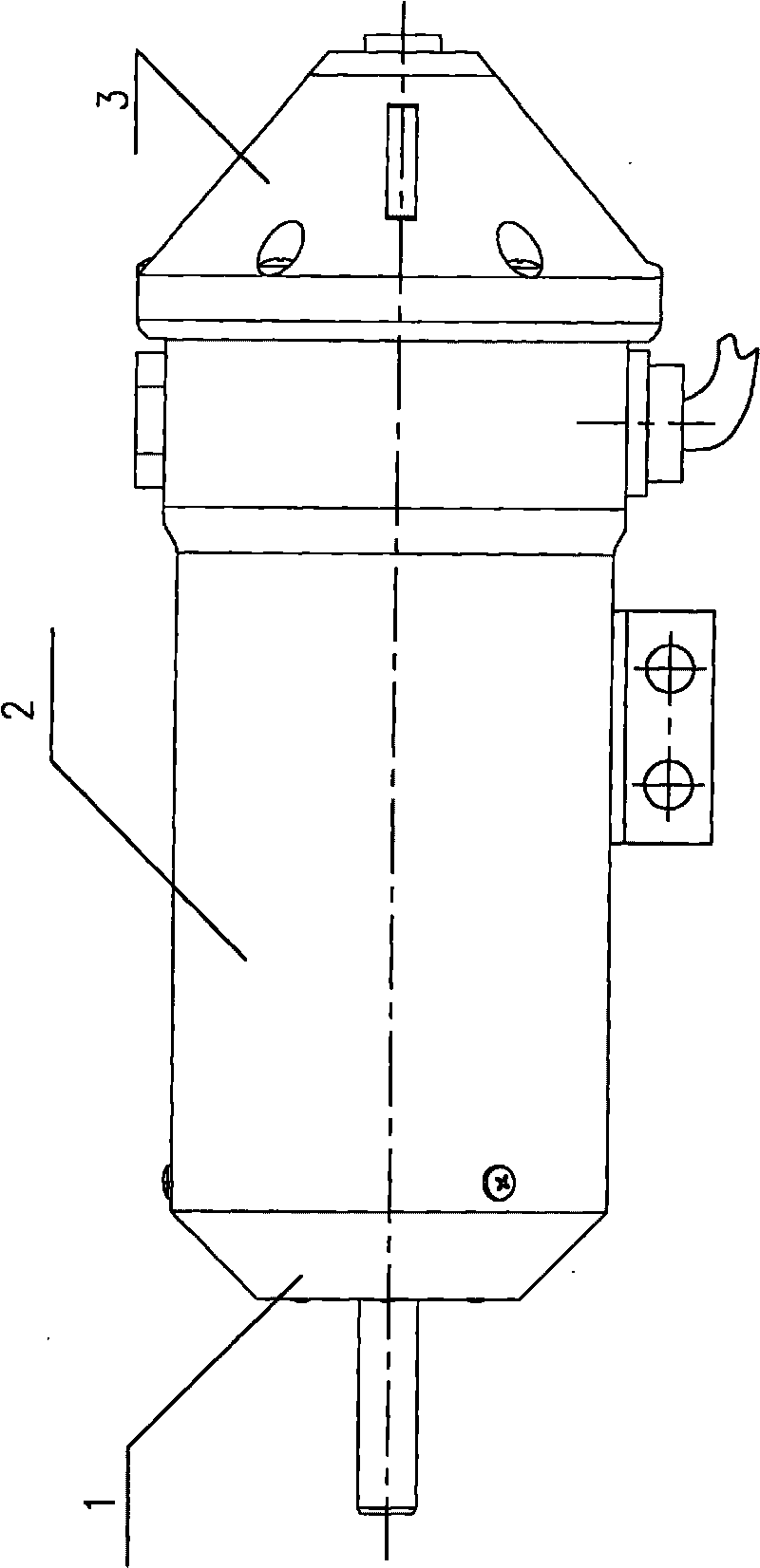
[0026] The structure of the motor adopts a modular design, and the main modules include a motor end cover assembly 1 , a motor body 2 and a compensator device 3 . Among them: the motor end cover assembly 1 is located at the front end of the motor, and is fixedly connected to the motor body 2 through the radial screws of the motor, and the interface position is radially statically sealed with an O-ring; the compensator device 3 is located at the tail of the motor, and is The axial screw is fixedly connected with the motor main body 2, and the interface position is statically sealed by compressing the sealing ring of the compensator bladder in the axial direction.

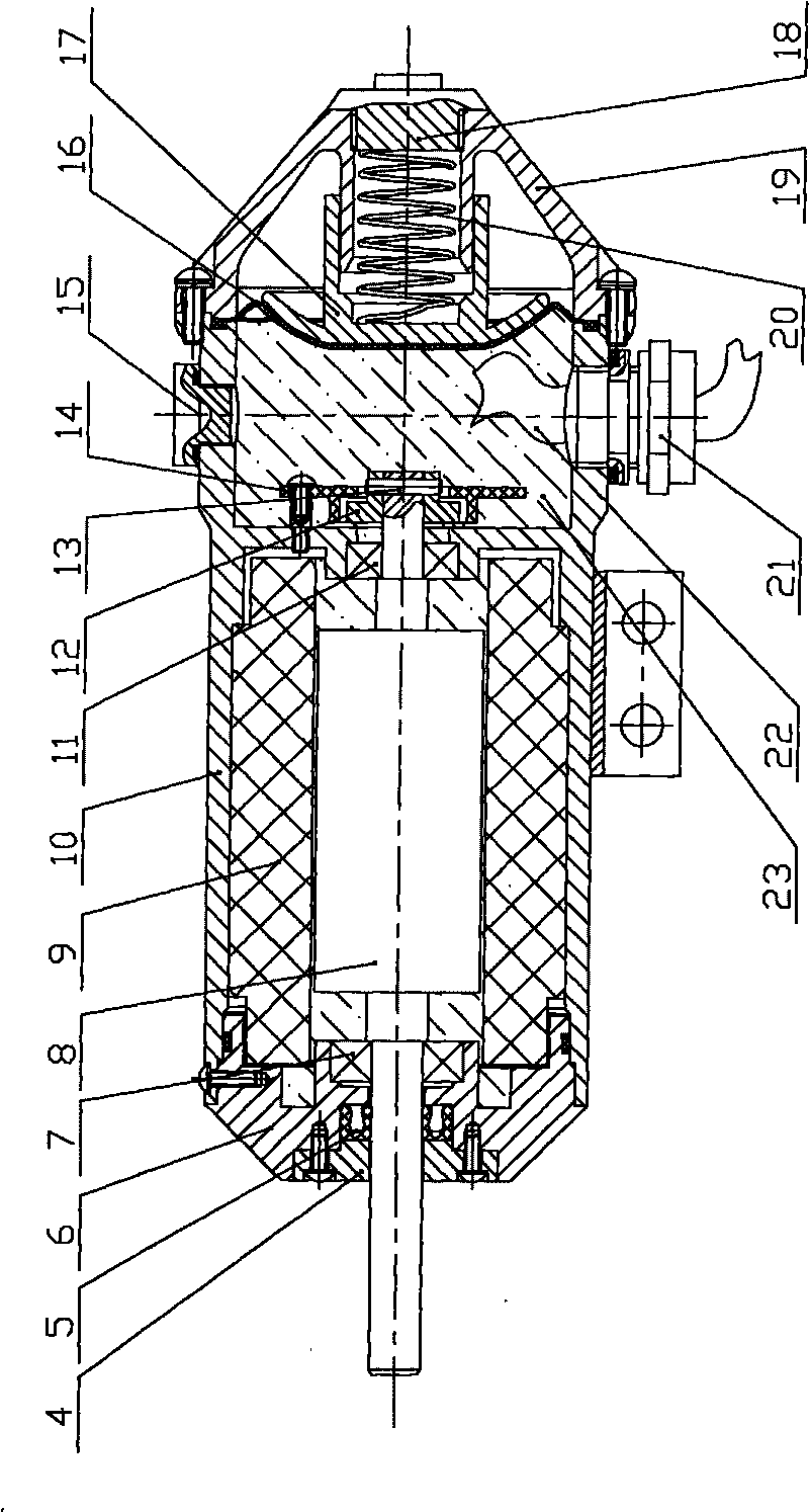
[0027] The motor end cover assembly 1 includes a motor end cover gland 4, a rotating seal body 5, a motor rotor front end bearing 7 and a motor end cover 6, wherein the motor rotor front end bearing 7 is positioned on the motor end cover 6 through the shoulder of the motor rotor...

Embodiment 2

[0030] Embodiment 2: assembly method

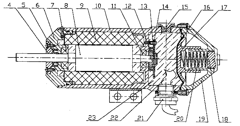
[0031] like figure 2 As shown, the motor stator 9 and the motor casing 10 are assembled into one body in a hot melt state; the motor rotor rear end bearing 11 is embedded in the bearing groove in the cavity of the motor casing 10; the motor rotor 8 is put into the inner cavity of the motor stator 9 , wherein the bottom end is embedded in the motor rotor rear end bearing 11; the magnetic ring 12 is fixedly connected to the motor rotor 8 through radial positioning rivets 13; the motor rotor front end bearing 7 is positioned in the bearing groove of the motor end cover 6; the rotating sealing body 5 is fixed in the sealing groove of the motor end cover 6 through the motor end cover gland 4 in such a way that the lip opening of 5 faces the inner side of the motor; the motor end cover gland 4 is fixedly connected to the motor end cover 6 with axial connecting screws; Under the guidance of the rotor 8 and the bearing 7 at the front end of the...


PUM


Abstract

The invention relates to a compensated underwater brushless DC motor structure and an assembly method thereof. The motor structure comprises a motor end cover subassembly (1), a motor main body (2) and a compensator device (3), wherein the motor end cover subassembly (1) is positioned at the front end of the motor main body (2) and is fixedly connected with the motor main body (2) via bolts, the compensator device (3) is positioned at the tail of the motor main body (2) and connected with the motor main body (2) via bolts, and the compensator device (3) comprises a compensator skin (16), a compensator gland bush (17), a motor tail hood (19), a compensator spring (20) and a compensator screw cap (18). The motor structure has modularized design characteristic, the compensator device and the motor main body can be separated, and different compensator devices can be correspondingly adjusted or replaced for meeting different work environmental requirements so that the motor structure has the advantages of simple and compact structure, convenient assembly and debugging, and safe and reliable working and easy maintenance.

Description

technical field [0001] The invention relates to an underwater brushless DC motor structure, in particular to a compensation type underwater brushless DC motor structure and an assembly method thereof. Background technique [0002] Motor drive is one of the commonly used driving methods for underwater working tools and equipment. Due to the influence of external seawater pressure under deep-sea working conditions, in order to meet the requirements of strength and stability, the motor housing in the form of a cavity usually has a large wall thickness, resulting in a relatively heavy motor in terms of volume and weight, and the motor shaft dynamic seal and motor efficiency be greatly affected. The pressure compensator is an auxiliary device that fills the inner cavity of the motor with oil and adjusts the pressure inside and outside the motor so that the pressure difference tends to meet the requirements of dynamic seal and shell strength. In the past, motors with inner cavit...

Claims


Application Information

Patent Timeline
Patent Type & Authority Applications(China)
IPC IPC(8): H02K5/132H02K5/10H02K11/00H02K29/08H02K11/20
Inventor 李硕唐元贵王棣棠张艾群陆国林
Owner SHENYANG INST OF AUTOMATION - CHINESE ACAD OF SCI
Why Eureka
Try Eureka