Large tuning range chirp signal generating method and device

A technology of chirp signal and generating device, applied in radio wave measurement systems, instruments, etc., can solve the problems of limited carrier frequency tuning performance and poor output signal stability, etc.

Active Publication Date: 2016-04-06
AIR FORCE UNIV PLA
View PDF3 Cites 15 Cited by
  • Summary
  • Abstract
  • Description
  • Claims
  • Application Information

AI Technical Summary

Problems solved by technology

[0005]However, the above solution has certain limitations
In the schemes 1) and 2), it is necessary to filter out optical signals of different wavelengths, and then modulate one of them. The system is a separate structure, and the stabili

Method used


Image

  • Large tuning range chirp signal generating method and device
  • Large tuning range chirp signal generating method and device
  • Large tuning range chirp signal generating method and device

Examples


Embodiment Construction

[0036] The present invention will be further described below in conjunction with accompanying drawing:

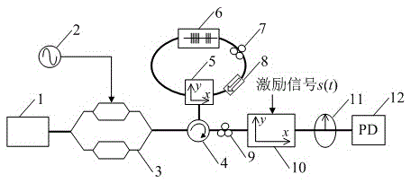
[0037] Such as figure 1 As shown, a large tuning range chirp signal generating device, including a wavelength tunable laser (1), a radio frequency local oscillator source (2), a dual-parallel Mach-Zehnder modulator (3), an optical circulator (4), a polarization Beam splitter (5), fiber Bragg grating (6), polarization controller B (7), polarization controller A (9), optical isolator (8), polarization modulator (10), analyzer (11) , a detector (12), a wavelength tunable laser (1), a radio frequency local oscillator source (2) are connected with a dual parallel Mach-Zehnder modulator (3); the dual parallel Mach-Zehnder modulator (3) is subjected to a radio frequency local oscillator Source (2) output signal modulation, dual parallel Mach-Zehnder modulator (3) output, optical circulator (4), polarization controller A (9), polarization modulator (10) are connected sequentially,...


PUM


Abstract

Provided are a large tuning range chirp signal generating method and device. The method comprises: in a large signal modulation mode, utilizing an electrooptical modulator to perform electrooptical modulation on the optical carrier wave outputted by a tunable light source and the radiofrequency signal outputted by a radio frequency local oscillator to obtain a dual wavelength optical signal; modulating the optical signal through a wavelength separation and polarization reuse module to generates an orthogonal polarization dual wavelength optical signal; employing the orthogonal polarization dual wavelength optical signal as an optical carrier wave to be inputted into a polarization modulator and to perform electro-optical modulation with a parabola waveform excitation signal; and generating a chirp signal through a detector beat frequency, and adjusting a tunable light source output wavelength and a radio frequency local oscillator output frequency to perform carrier frequency tuning on a generated chirp signal. The chirp signal generated in the scheme has the advantages of great stability, high carrier frequency, large tuning range, reconstructible waveform, etc., and can be applied widely in future.

Description

technical field [0001] The invention belongs to the technical field of microwave photon signal generation, and in particular relates to a method and a device for generating a chirp signal with a carrier frequency having a large tuning range. Background technique [0002] Chirp signal is one of the most commonly used radar signal forms. It has a large time-width bandwidth product, which can improve the measurement accuracy and resolution of radar distance and speed at the same time. On the other hand, chirp signal has excellent pulse compression Features, can improve the range and measurement accuracy of the radar at the same time. With the continuous development of technology, the functional requirements of radar equipment are getting higher and higher, especially in the field of military combat, it is urgent to improve the "four resistance" capabilities of radar such as anti-electronic interference, anti-stealth, anti-low-altitude penetration, and anti-radiation missiles. ...

Claims


Application Information

Patent Timeline
IPC IPC(8): G01S7/484
CPCG01S7/484
Inventor 李轩赵尚弘潘时龙朱子行李勇军
Owner AIR FORCE UNIV PLA
Why Eureka
Try Eureka