Step motor controlled driving circuit

A driving circuit and stepping motor technology, which is applied in the direction of motor generator control, control system, electrical components, etc., can solve the problem of high power consumption of stepping motors, and achieve the effects of low software requirements, reduced heat dissipation requirements, and large driving torque

Active Publication Date: 2010-06-23
NO 11 INST OF NO 6 ACADEMY OF CHINA AEROSPACE SCI & TECH
View PDF0 Cites 9 Cited by
  • Summary
  • Abstract
  • Description
  • Claims
  • Application Information

AI Technical Summary

Problems solved by technology

[0003] The purpose of the invention is to provide a stepper motor control drive circuit, which solves the technical problem of high power consumption of the existing stepper motor,

Method used


Image

  • Step motor controlled driving circuit
  • Step motor controlled driving circuit
  • Step motor controlled driving circuit

Examples


Embodiment Construction

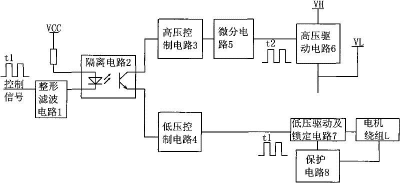
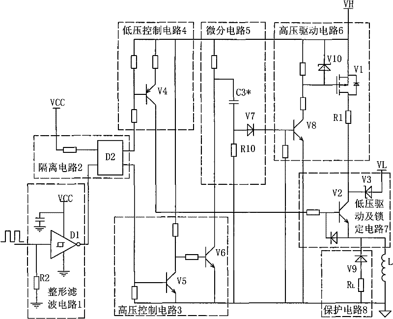
[0024] The stepper motor control driving circuit of the present invention includes a shaping filter circuit 1, an isolation circuit 2, a low-voltage control circuit 4, a high-voltage control circuit 3, a differential circuit 5, a high-voltage driving circuit 6, a low-voltage driving and locking circuit 7, and a protection circuit 8; The shaping filter circuit 1 includes a Schmitt trigger inverter D1 and a port protection resistor R2, the input terminal of the Schmitt trigger inverter D1 is connected to the control pulse signal, and its output terminal is connected to the low end of the input signal of the photocoupler D2; the port One end of the protection resistor R2 is connected to the input end of the Schmitt trigger inverter D1, and the other end is grounded; the isolation circuit 2 includes a photocoupler D2; the high end of the input signal of the photocoupler D2 is connected to the signal power supply VCC; the low voltage control circuit 4 includes The third triode V4; t...


PUM


Abstract

The invention relates to a step motor controlled driving circuit, which comprises an isolation circuit (2), a low-voltage control circuit (4), a high-voltage control circuit (3), a differentiating circuit (5), a high-voltage driving circuit (6) and a low-voltage driving and locking circuit (7). The step motor controlled driving circuit solves the technical problem of high power consumption of the existing step motor, and has the advantages of low controller software requirement, low power consumption, large driving torque, capacity of maintaining balanced torque, lower radiating requirement on a power supply and the driving circuit, and high reliability.

Description

technical field [0001] The invention relates to a stepper motor control driving circuit. Background technique [0002] The stepper motor drive control method widely used now has the disadvantages of large output torque but high power consumption; some drive control methods have high drive performance, but the circuit and control software are complex, resulting in reduced overall reliability; To meet the requirements of high performance, high output torque and low power consumption, it is necessary to develop a stepper motor drive control circuit. The reactive stepper motor itself has no self-locking torque, so it is necessary to apply a certain current to both ends of the winding to maintain a certain torque during the rotation process and the static process. Especially in the static process, the winding current is all converted into heat dissipation, which has higher requirements on the heat dissipation of the power supply and drive circuit. If the stepper motor is powere...

Claims


Application Information

Patent Timeline
Patent Type & Authority Applications(China)
IPC IPC(8): H02P8/14H02P8/12
Inventor 刘军
Owner NO 11 INST OF NO 6 ACADEMY OF CHINA AEROSPACE SCI & TECH
Why Eureka
Try Eureka