
Inertia estimating controller and control system

A control device and motor technology, which is applied in the field of inertia estimation control devices and control systems, and can solve problems such as the reduction of detection accuracy

Active Publication Date: 2010-06-23
FANUC LTD
View PDF2 Cites 14 Cited by
  • Summary
  • Abstract
  • Description
  • Claims
  • Application Information

AI Technical Summary

Problems solved by technology

In the case of estimating inertia, current feedback or speed feedback is used, but they contain noise, which may degrade detection accuracy

Method used


Image

  • Inertia estimating controller and control system
  • Inertia estimating controller and control system
  • Inertia estimating controller and control system

Examples


Embodiment Construction

[0026] Embodiments of the present invention will be described below with reference to the drawings.

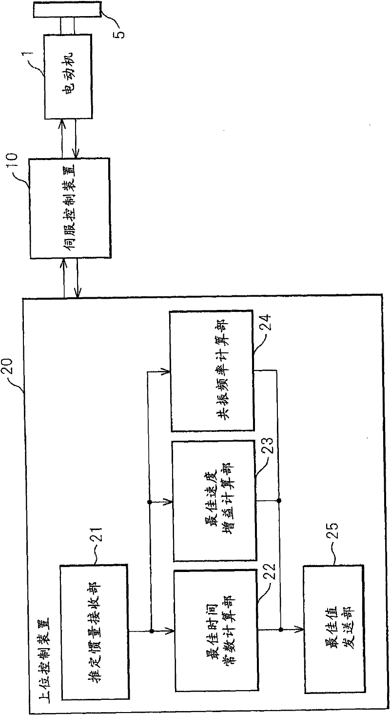
[0027] figure 1 It is a block diagram showing the structure of the control system of this embodiment. As shown in the figure, the control object in this embodiment is the motor 1 that operates the driven body 5 . The motor 1 is used, for example, to change the position or posture of a table holding a workpiece in a machine tool, or to rotate an arm of a robot. The driven body 5 driven by the motor 1 may include a table, a robot arm, and a workpiece that can be mounted or detached thereon, and may also include an operating part of the motor 1 itself.

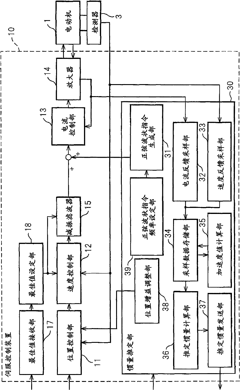
[0028] The position, speed and torque of the motor 1 are controlled by a servo control device 10 . The servo control device 10 is connected to a host control device 20 such as a CNC (numerical control device) or an external device that issues commands for the position, speed, and torque of the motor 1 in accordance with the wo...


PUM


Abstract

A controller and a control system capable of estimating inertia of an article to be driven in a short period of time, with a small operation range of an electric motor. The controller for the motor has an inertia estimating part which includes a sine-wave command generating part which adds a sine-wave command to a torque command for the motor; a current feedback sampling part which obtains a current value of the motor; a speed feedback sampling part which obtains a speed feedback of the motor; an acceleration calculating part which calculates an acceleration value based on the speed feedback; and an estimated inertia calculating part which estimates the inertia of the article, based on a representative current value, a representative acceleration value and a torque constant of the motor, which are calculated from current and acceleration values in a plurality of cycles of the sine-wave command and stored in a sampling data storing part.

Description

technical field [0001] The present invention relates to a motor control device and control system for operating mechanical parts in industrial machines such as machine tools, and more particularly to a control device and control system for estimating inertia of a driven body driven by a motor. Background technique [0002] In machine tools, knowing the inertia of a driven body driven by a motor is crucial for determining machining conditions and controlling the drive shaft corresponding to the motor with high precision. For example, when determining the time constant of an acceleration / deceleration command as a machining condition, it is advantageous to accurately know the inertia in order to perform stable control and fully utilize the acceleration / deceleration capability of the motor. In addition, accurate knowledge of the inertia is also beneficial in calculating the gain in the control system that determines the responsiveness of the speed control. [0003] However, it ...

Claims


Application Information

Patent Timeline
Patent Type & Authority Applications(China)
IPC IPC(8): H02P23/14H02P29/00
CPCG05B19/404G05B2219/37621G05B2219/37388
Inventor 置田肇丰泽雪雄园田直人
Owner FANUC LTD
Learn More