Distortion compensation apparatus and method
A technology of distortion compensation and series, which is applied in amplitude adaptive pre-distortion, components of amplification devices, look-up table adaptive pre-distortion, etc., which can solve problems such as inability to maintain sufficient performance of distortion compensation and increase of out-of-band radiation power
- Summary
- Abstract
- Description
- Claims
- Application Information
AI Technical Summary
Problems solved by technology
Method used
Image
Examples
no. 1 approach
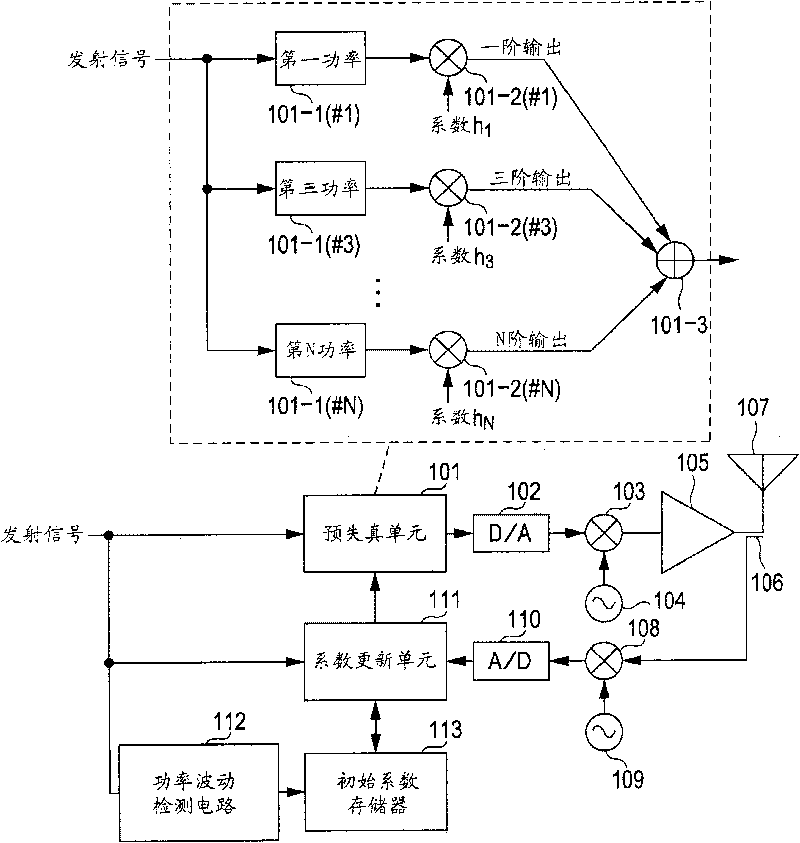
[0045] figure 1 is a configuration diagram of the first embodiment of the distortion compensation device.
[0046] The predistortion unit 101 performs a power series operation consisting of odd-order power terms, and is composed of a power calculation unit 101-1, a coefficient multiplier 101-2, and an accumulator 101-3. The predistortion unit 101 therefore performs distortion compensation of the transmit amplifier 105 .
[0047] The output of the pre-distortion unit 101 is converted into an analog signal by the D / A converter 102, and further quadrature modulated by the quadrature modulator 103 based on the signal oscillated by the local oscillator 104 according to the transmitting base station.
[0048] The transmission amplifier 105 amplifies the power of the modulated transmission analog signal, and its output is provided to the transmission antenna 107 via the coupler 106, and then transmitted therefrom.
[0049] In addition, feedback of the output of the transmission am...
no. 2 approach
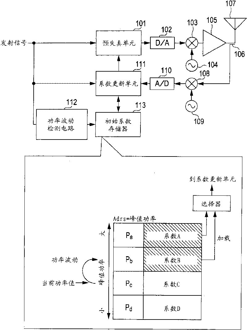
[0055] figure 2 is a configuration diagram of a second embodiment of the distortion compensation device. The second embodiment and figure 1 The difference from the first embodiment in is in the structure related to the distortion compensation coefficients stored in the initial coefficient memory 113 . exist figure 2 , append the same number as the figure 1 The units in the same unit.
[0056] In this embodiment, if figure 2 As shown, the initial coefficient memory 113 stores a corresponding set of power series operation coefficients for each power level of the transmitted signal. exist figure 2 In the embodiment of , corresponding coefficients A, B, C and D are stored for four power levels (peak power levels are Pa, Pb, Pc and Pd). Each coefficient is a power series operation coefficient group. figure 2 An embodiment is illustrated in which the peak power of the transmitted signal fluctuates from Pc to Pb. A coefficient (coefficient A or coefficient B) correspo...
no. 3 approach
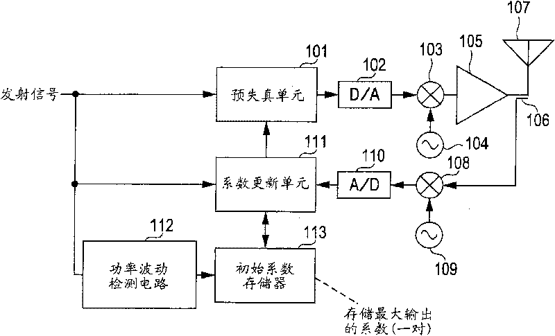
[0059] image 3 is a configuration diagram of a third embodiment of the distortion compensation device. The third embodiment and figure 1 The difference from the first embodiment in is in the structure related to the distortion compensation coefficients stored in the initial coefficient memory 113 . exist image 3 , append the same number as the figure 1 The units in the same unit.
[0060] exist image 3 , only coefficients corresponding to the maximum output power of the transmit amplifier 105 are held in the initial coefficient memory 113 . Then, when power fluctuation occurs, regardless of the power value after fluctuation, the coefficient corresponding to the maximum output power is read from the initial coefficient memory 113 and input to the coefficient updating unit 111 .
[0061] In the present embodiment, since only one set of coefficients is held in the initial coefficient memory 113, the increase of the out-of-band radiation power is greater than in the sec...
PUM
 Abstract
Description
Claims
Application Information
 - R&D
- Intellectual Property
- Life Sciences
- Materials
- Tech Scout
- Unparalleled Data Quality
- Higher Quality Content
- 60% Fewer Hallucinations
Browse by: Latest US Patents, China's latest patents, Technical Efficacy Thesaurus, Application Domain, Technology Topic, Popular Technical Reports.
© 2025 PatSnap. All rights reserved.Legal|Privacy policy|Modern Slavery Act Transparency Statement|Sitemap|About US| Contact US: help@patsnap.com


