
Apparatus for adjusting the degree of freedom using sensor in assembling optical device

An optical device, a technology of degrees of freedom, applied in the directions of optics, optical components, installation, etc., can solve problems such as difficulty in adjusting degrees of freedom, deterioration of image quality, and image distortion, and achieve the effect of overcoming image distortion.

Inactive Publication Date: 2010-06-23
ADS TECH
View PDF0 Cites 13 Cited by
  • Summary
  • Abstract
  • Description
  • Claims
  • Application Information

AI Technical Summary

Problems solved by technology

The problem comes from the fact that the image sensor is being assembled on the PCB, but it is not properly bonded to the PCB in three or six axis degrees of freedom, such as slope angle, height, width, depth, rotation, etc. etc., and the adjustment of this degree of freedom is also a very difficult task
[0006] Therefore, since the position of the degree of freedom in three or six axes changes along with the focal length of the lens when assembling the PCB assembly on which the image sensor is mounted and the lens assembly, image distortion occurs, thereby deteriorating the image quality

Method used


Image

  • Apparatus for adjusting the degree of freedom using sensor in assembling optical device
  • Apparatus for adjusting the degree of freedom using sensor in assembling optical device
  • Apparatus for adjusting the degree of freedom using sensor in assembling optical device

Examples


Embodiment Construction

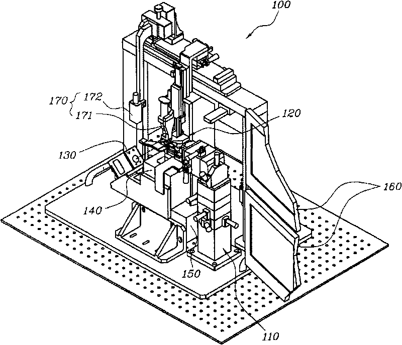
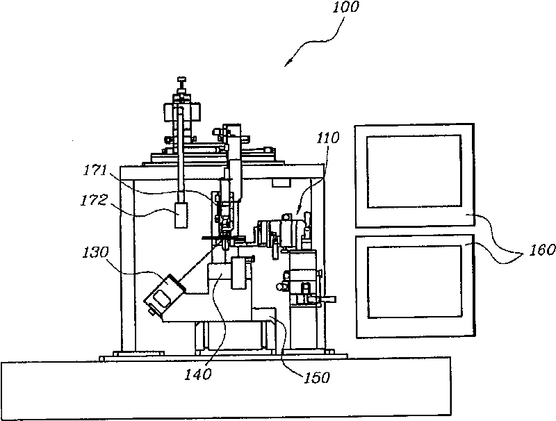
[0030] Such as Figure 1 to Figure 8 As shown, the optical arrangement using the device 100 according to the present invention to adjust the degree of freedom by the sensor during assembly comprises: a printed circuit board (PCB) assembly 10 having a PCB board 11 and an image surface mounted on the PCB board 11 The sensor 12 ; the lens assembly 20 ; and the fixing plate 30 as a connection medium connecting the lens assembly 20 to the PCB assembly 10 .

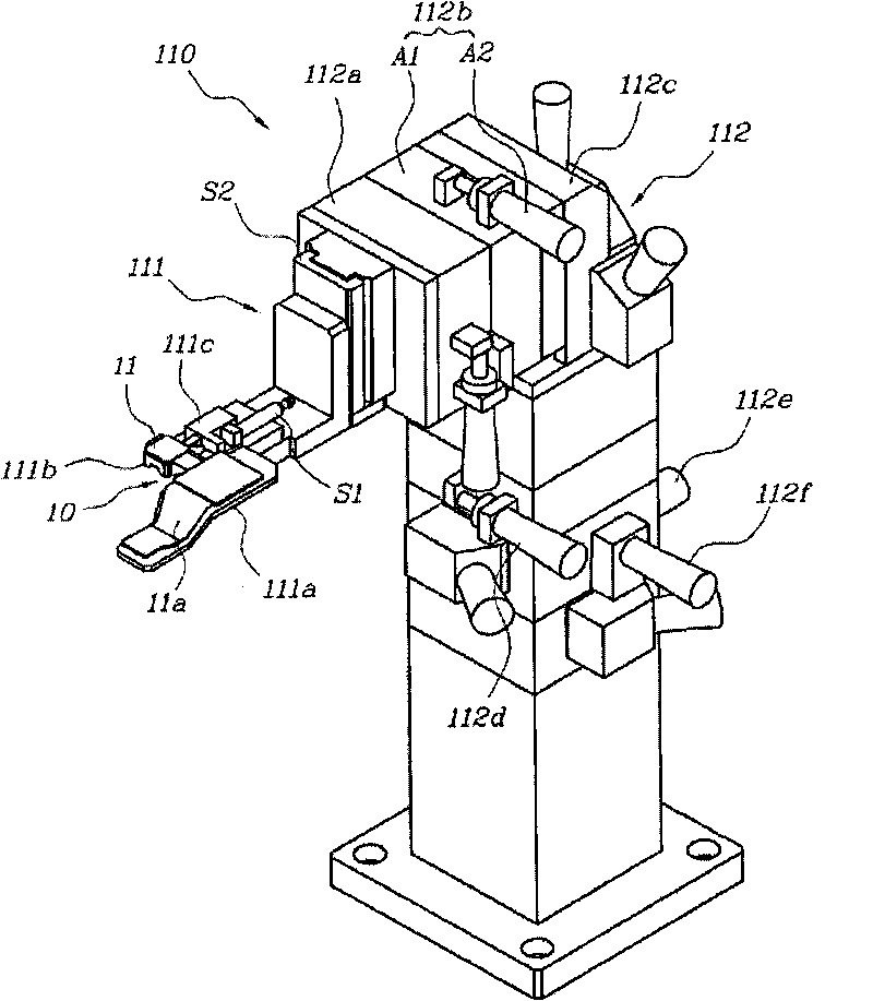
[0031] The device 100 also includes: a degree of freedom adjustment unit 110, the degree of freedom adjustment unit 110 has a holder 111 and an error control part 112 connected to the holder 111, the holder 111 is used to firmly support the PCB assembly 10, and the error control part 112 is used to During the surface mount image sensor 12, the error is corrected by controlling the position of the holder 111 to adjust the degree of freedom; the board fixing unit 120, the board fixing unit 120 has a fixing jig 121 for firmly load...


PUM


Abstract

An apparatus for adjusting degrees-of-freedom during the assembly of an optical device using a sensor. The apparatus includes a degree-of-freedom adjustment unit having a holder and an error control portion linked with the holder; a plate-fixing unit having a fixed jig for firmly loading the fastening plate, an elevating means and a plunger for fixing the fastening plate; a laser generating unit for emitting a laser beam onto the image sensor on the PCB assembly which is loaded on the holder; a sensor unit for measuring a mounted status of the image sensor surface-mounted on the PCB plate; and a control unit displaying a current position and a quality decision factor of the image sensor on a monitor after comparing a measured value transmitted from the sensor unit with a previously established master reference value.

Description

technical field [0001] The present invention relates to an apparatus for adjusting the degree of freedom of an image sensor during assembly of an optical device of a digital camera, and more particularly, to an apparatus for adjusting a degree of freedom using a sensor during assembly of an optical device in which the position of the image sensor is detected by using a laser beam and By adjusting the current state, the mutual positions of the lens assembly and the surface-mounted image sensor on the PCB board can be accurately bonded, so that optical products with good quality can be mass-produced without distortion effects. Background technique [0002] During a typical manufacturing process of optical devices such as digital cameras and printed circuit boards (PCBs), image sensors and optical lens assemblies are connected and assembled together. [0003] Specifically, a PCB assembly is formed by surface-mounting an image sensor as an imaging element on a PCB printed with l...

Claims


Application Information

Patent Timeline
Patent Type & Authority Applications(China)
IPC IPC(8): G02B7/02
Inventor 崔熙瓒宋光烈
Owner ADS TECH
Learn More