Pinhole type imaging device

a pinhole type, imaging device technology, applied in the direction of instruments, material analysis, television systems, etc., can solve the problems of inability to obtain sharp images of objects not positioned at the fixed distance, inability to obtain sharp images, complicated structure, etc., to achieve simple structure, long life in use, compact size

Inactive Publication Date: 2007-07-05
TECHNO INT +1
View PDF10 Cites 3 Cited by
  • Summary
  • Abstract
  • Description
  • Claims
  • Application Information

AI Technical Summary

Benefits of technology

[0016] Since the above structure is adopted in the present invention, the present invention has such a feature that, when light rays pass through the pinhole type aperture stop, both imaging of light rays which are advanced from a remote object into the optical system and imaging of light rays which are advanced from a close object into the optical system are sharp, and all images of subjects positioned at different distances are simultaneously made sharp. Simultaneously therewith, since such a defect that distortion is large in an ordinary pinhole can overcome by optical lenses attached at a front end and a rear end of the pinhole, it is possible to cause an entire photosensitive area of a sensor element to receive an image obtained by the imaging device of the present invention.
[0017] Since the present invention includes such an advantage that neither an auto-focusing system mechanism nor a manually focusing system mechanism is required, so that a structure is simple, a size is compact, a life in use is long, and a cost is reduced, the imaging device of the present invention is suitable for attachment and use in an information or data processing terminal such as such as a small-sized image pickup device, a portable phone (a cellular phone), or a mobile type computer, and an auxiliary device thereof.

Problems solved by technology

According to a conventional art, however, there are the following problems.
(1) When a subject positioned at a fixed distance is photographed, there is a problem that a sharp image of an object which is not positioned at the fixed distance can not be obtained.
(2) Even if assistance of the mechanical devices is utilized, there is such a problem that a sharp image of an object at the fixed photographing distance is only obtained, and such a merit that imaging results of an object relatively close to the fixed photographing distance and an object relatively distant therefrom are sharp can not be obtained.
(3) Since an image device having an auto-focusing and manually focusing optical device structure is provided with an exclusive mechanical structure for auto-focusing function and manual focusing function, such as a step motor, a VCM actuator, a manual focusing slide rod, and the like, there is a such a problem that a structure thereof is complicated, a size thereof is large, and a manufacturing cost is increased.
However, since the mobile type electronic equipment is limited by its volume, there is a further strong demand for small sizing and simplification of the imaging device.

Method used


Image

  • Pinhole type imaging device
  • Pinhole type imaging device
  • Pinhole type imaging device

Examples


example 1

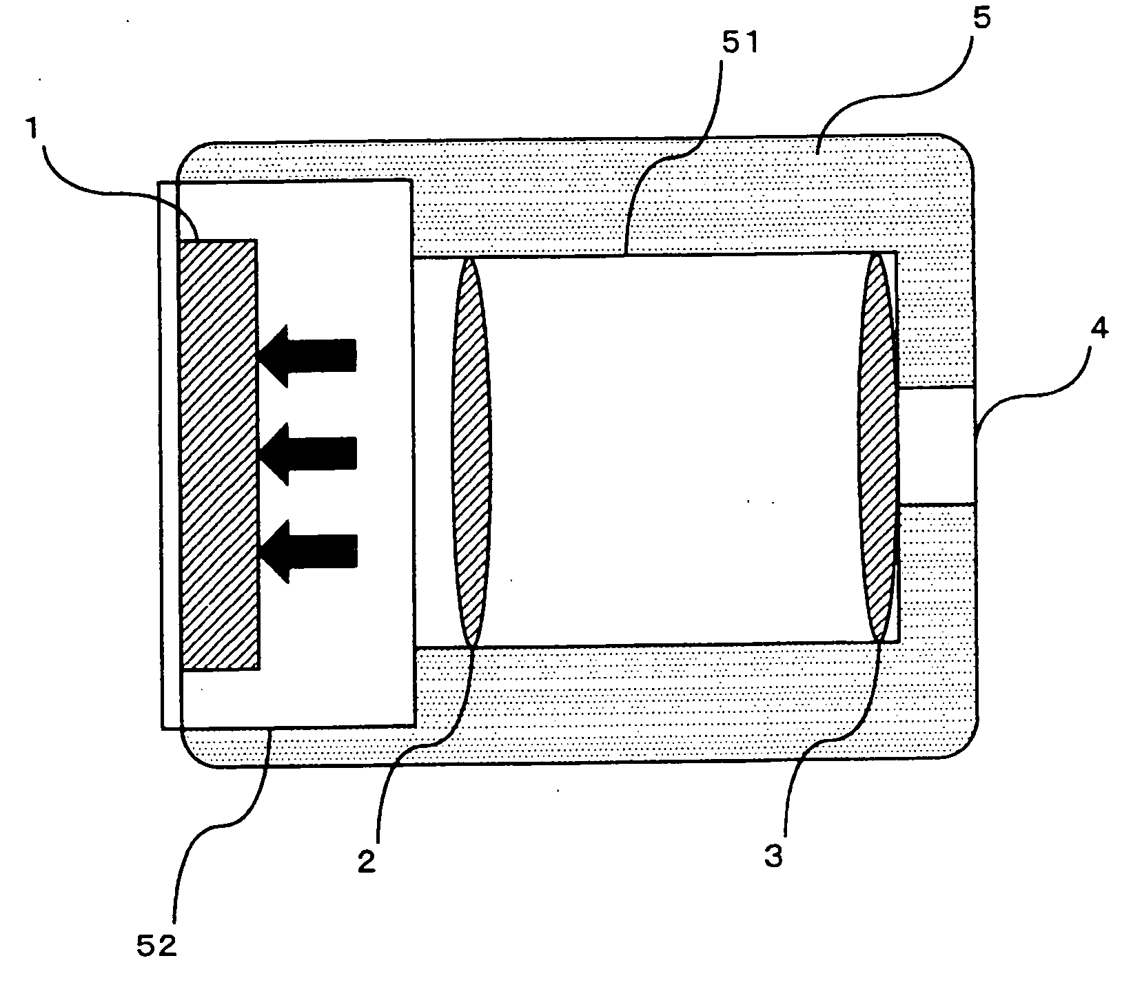
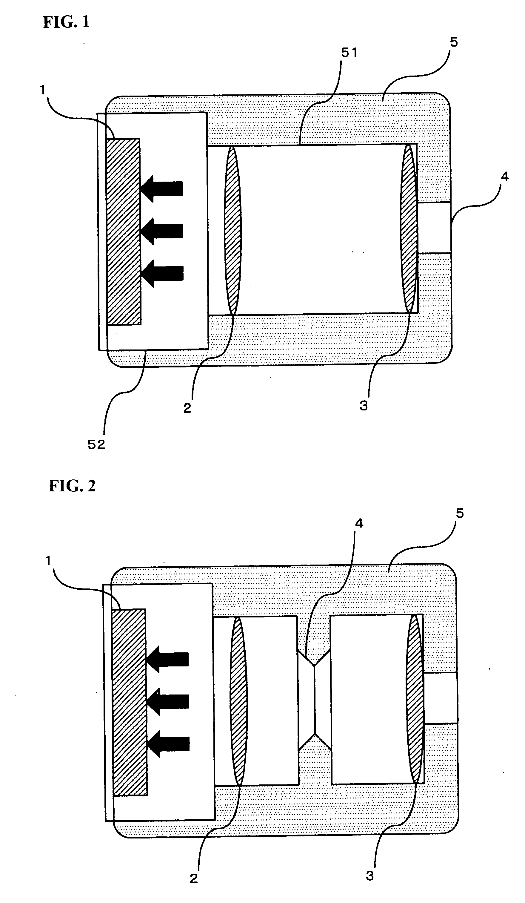
[0028]FIG. 1 shows a pinhole type imaging device with two optical lenses, where a pinhole 4 with a diameter of 0.8 mm is formed at a distal end of a main unit 5, and a depth of the pinhole 4 is set to 2 mm. A rear end of the pinhole 4 is expanded to constitute a lens cylinder 51 with a large diameter. A rear end of the lens cylinder 51 is further expanded to constitute an accommodation space 52 with a large diameter for a photoelectric converting sensor 1. Optical lenses 3 and 2 are sequentially fitted into the lens cylinder 51 from a rear portion of the main unit 5 and the photoelectric converting sensor 1 is disposed in the accommodation space 52. The main unit 5 is integrally formed from opaque material and it constitutes a light shielding wall for preventing light rays from advancing from a portion of the main unit 5 other than the pinhole.

[0029] When the pinhole type imaging device of Example 1 is used, light rays from a subject within a visible range (an object to be photogra...

example 2

[0030]FIG. 2 shows another Example of the pinhole type imaging device according to the present invention, and it is different from the Example 1 in that two optical lenses 2 and 3 are provided at front and rear ends of the pinhole 4 in the former. The optical lens 2 is fitted at a distal end of the main unit 5, and a pinhole 4 with a diameter of 0.75 mm is formed concentrically with the optical lens 2 behind the optical lens 2, where a depth of the pinhole 4 is set to 3 mm. A rear end of the pinhole 4 is expanded to constitute a lens cylinder 51, and a rear end of the lens cylinder 51 is further expanded to constitute an accommodation space 52 with a large diameter for a photoelectric converting sensor 1. The optical lens 3 is fitted into the lens cylinder 51 from a rear portion of the main unit 5, and the photoelectric converting sensor 1 is disposed in the accommodating space 52. The main unit 5 is integrally formed from opaque material and it constitutes a light shielding wall fo...

example 3

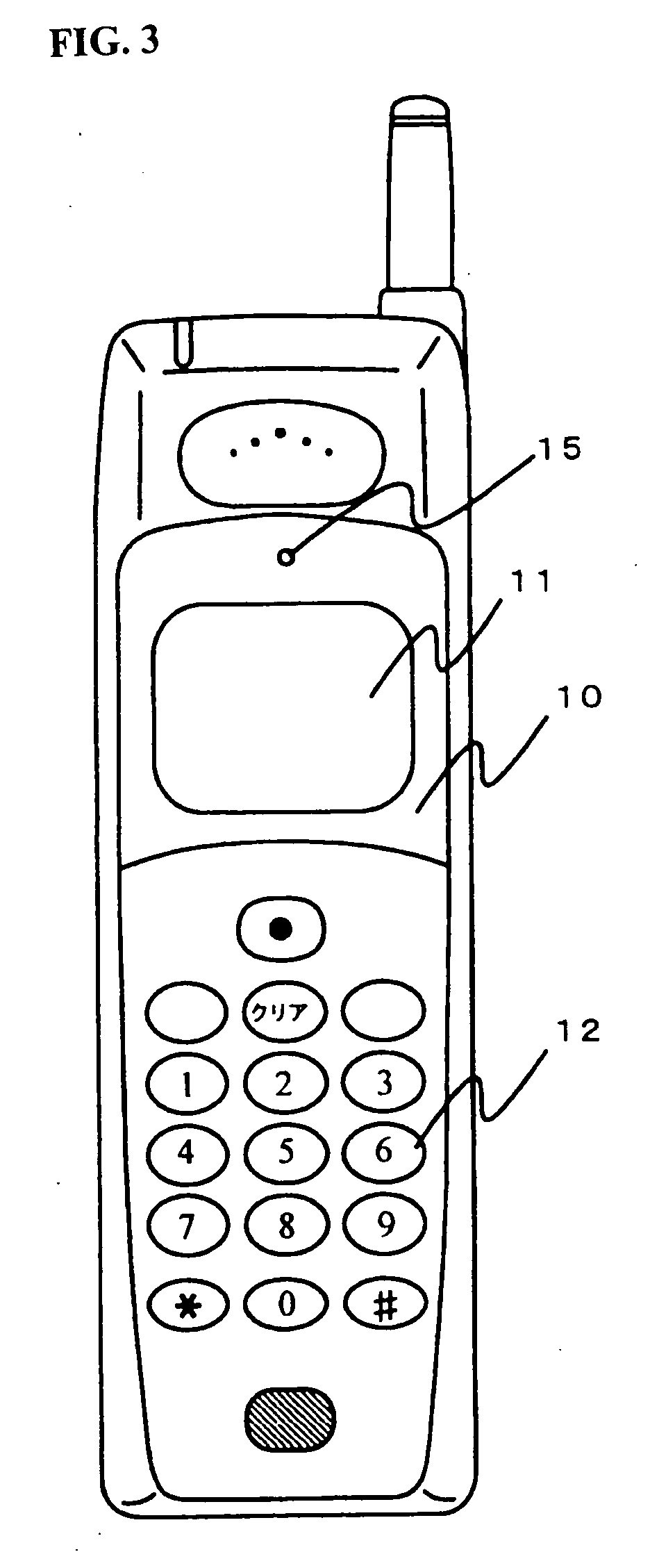
[0031]FIG. 3 and FIG. 4 shows an Example of a cellular phone applied with the pinhole type imaging device of the present invention.

[0032] The cellular phone has a casing 10 whose front face is provided with a display unit 11, an operation unit 12, and a pinhole unit 15.

[0033] The pinhole unit 15 is formed at an upper end with a pinhole 19 with a diameter of 0.8 mm, and a convex lens 16 is fittingly provided on the opposite face of the pinhole type aperture stop from a subject side. An accommodation space for a CCD image sensor 18 is defined at a lower portion of the pinhole unit 15, a filter glass 181 and a sensor unit 182 are included in the CCD image sensor 18, and the sensor unit 182 is fixed to a main base plate 17, and the filter glass 181 is disposed above the sensor unit 182.

[0034] A storage unit or a chip of the cellular phone which stores image data produced from image signals obtained by an image photographed by a corresponding CCD image sensor 18 or a signal processing...


PUM


Abstract

A pinhole type imaging device of the present invention includes a pinhole type aperture stop which allows advancing of light ray into an optical system and imaging, and at least one lens which is attached to the pinhole type aperture stop. Accordingly, an imaging device where it is realized that all imaging results of subjects positioned at different photographing distances are sharp, which has a simple structure and can be reduced in size, and which is suitable for attachment or use in an information terminal such as a small-sized image pickup device, a portable phone (a cellular phone), or a mobile type computer, and an auxiliary device thereof.

Description

BACKGROUND OF THE INVENTION 1. Field of the Invention [0001] The present invention relates to an imaging device, and in particular to an imaging device having a pinhole type lens. 2. Description of the Related Art [0002] Imaging based upon an optical lens system is currently adopted in many of ordinary image pick-up devices, where, only when photographing is performed at a fixed photographing distance, a sharp imaging result of an object positioned at the fixed photographing distance or near the same can be obtained. [0003] According to a conventional art, however, there are the following problems. [0004] (1) When a subject positioned at a fixed distance is photographed, there is a problem that a sharp image of an object which is not positioned at the fixed distance can not be obtained. When sharp images of all objects positioned at different photographing distances are tried to be obtained, assistance of a series of mechanical devices, for example, an auto-focusing device or a lens...

Claims


Application Information

Patent Timeline
Patent Type & Authority Applications(United States)
IPC IPC(8): H01L27/00
CPCH01L27/14618H01L27/14625H04N5/2257H04N5/2254H01L27/14868H01L2924/0002H04N23/57H04N23/55H01L2924/00
Inventor ABE, CHIAKI
Owner TECHNO INT
Why Eureka
Try Eureka