Method and apparatus for reactive optical correction of galvano motor scanning heads

Inactive Publication Date: 2010-09-02
ABARISCAN
View PDF5 Cites 5 Cited by
  • Summary
  • Abstract
  • Description
  • Claims
  • Application Information

AI Technical Summary

Benefits of technology

[0007]A method is provided for the optical correction of field position distortions created by galvano motor scanning heads to achieve a calibration of said field position to overcome said distortions generated by the delivery optics within a galvano motor scanning head using a pre-calibrated target that may be positioned into a registration or ‘lay’ system for ease of identifying and measuring a series of marks by removal and replacing said pre-calibrated target into said registration or ‘lay’ system, pre-determined logic means to generate said series of marks on said pre-calibrated target using said galvano motor scanning head and galvano motor scanning head and laser control apparatus, and operator inputs so that said logic means can calculate from a minimum number of operator entries into said logic means corresponding to said series of marks on said pre-calibrated target a full field correction of the field position distortions taking into account all beam or laser beam, mounting, alignment and parallelity intolerances to generate corrected galvano motor position control optical correction data reactive to the exact parameters of an individual laser, delivery optic / s, galvano motor scanning head and target plane set-up and without the need for any design parameters or data of the optics or optical set-up in use.

Problems solved by technology

Firstly, in the case of pre-objective scanning where a flat-field or f-Theta or telecentric lens or lenses are used and because the pre-calculated or proactive galvano motor driven scanning head correction data is commonly generated by knowing the galvano motor driven deflection mirror separation distances, the galvano motor driven deflection mirror scanning angles, the final galvano motor driven mirror separation distance to said flat-field or f-Theta or telecentric lens or lenses and the design parameters of said flat-field or f-Theta or telecentric lens or lenses any pre-calculated or proactive galvano motor driven scanning head correction data will not take into account any intolerances of the beam or laser beam or galvano motor mounting or optical mounting or parallelity between the galvano motor driven scanning head and the target plane.
Secondly, in the case of post-objective scanning where an active or passive telescope comprising a series of lenses is used, and because the pre-calculated or proactive galvano motor driven scanning head correction data is commonly generated by knowing the telescope lens element design parameters and separation distances, the galvano motor driven deflection mirror separation distances, the galvano motor driven deflection mirror scanning angles, and the final galvano motor driven mirror separation distance to the target plane any pre-calculated or proactive galvano motor driven scanning head correction data will not take into account any intolerances of the beam or laser beam or galvano motor mounting or optical mounting or parallelity between the galvano motor driven scanning head and the target plane.
Third, because said process of pre-objective or post-objective galvano motor scanning head correction data is pre-calculated and hence proactive any field distortions remaining after said pre-objective or post-objective galvano motor scanning head correction data is generated and applied due to any intolerances must be further corrected by a complex process of marking, measuring and inputting fresh data into said pre-objective or post-objective galvano motor scanning head correction data to apply further corrections to perfectly match said pre-objective or post-objective galvano motor scanning head correction data to further correct for said intolerances to achieve distortion free targeting.
Fourth, because said pre-objective or post-objective galvano motor scanning head correction data is pre-calculated and hence proactive said pre-objective or post-objective galvano motor scanning head correction data must be generated knowing the design parameters of optics that optic manufacturers do not commonly wish to divulge.

Method used


Image

  • Method and apparatus for reactive optical correction of galvano motor scanning heads
  • Method and apparatus for reactive optical correction of galvano motor scanning heads
  • Method and apparatus for reactive optical correction of galvano motor scanning heads

Examples


Embodiment Construction

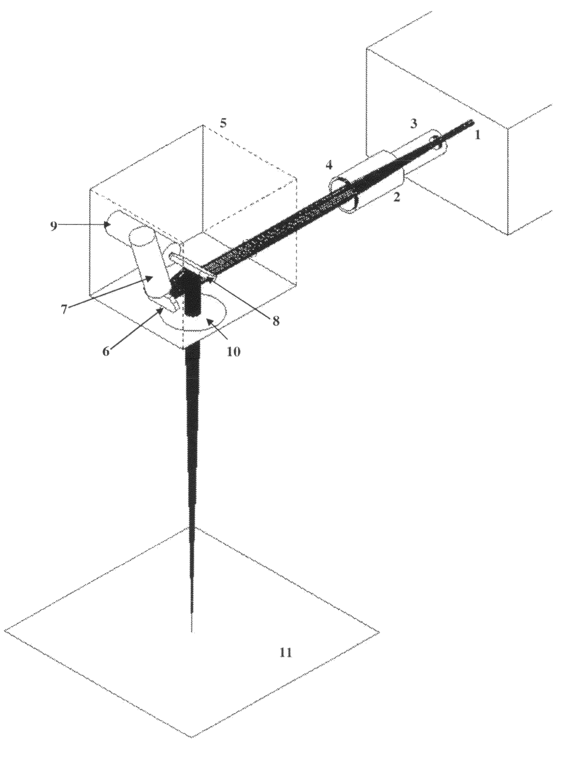
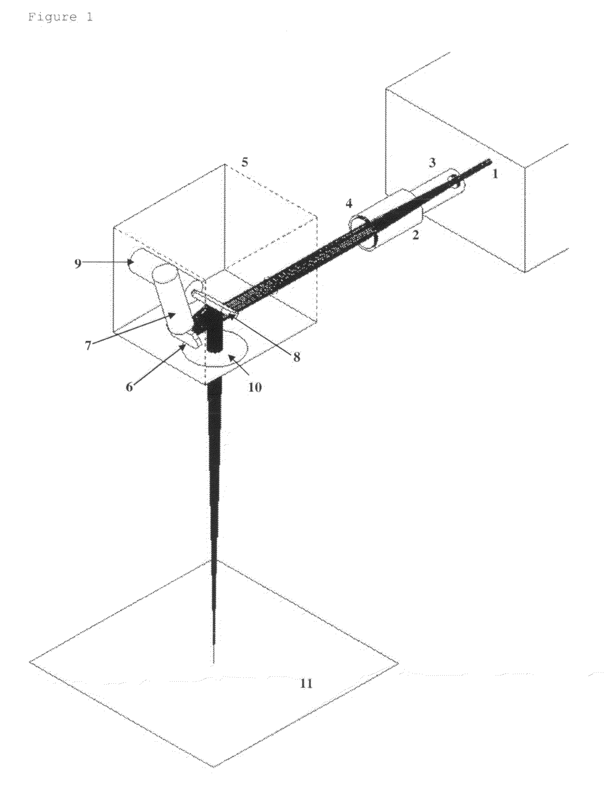
[0025]As depicted in FIG. 1, a beam or laser beam (1) being diverging, collimated or converging enters a galvano motor scanning head (5) either directly or first passing through beam or laser beam delivery optics in this embodiment shown as a two-element beamexpander (2) comprising in this embodiment an entry optical element (3) to expand said beam or laser beam (1) and an output collimating optical element (4) so that the beam or laser beam (1) then inside said galvano motor scanning head (5) in this embodiment deflecting off a first or X galvano motor driven mirror (6) attached to a first or X galvano motor (7) and steered to deflect off a second or Y galvano motor driven mirror (8) attached to a second or Y galvano motor (9) and steered to deflect to transmit through in this pre-objective scanning embodiment a flat-field or f-Theta or telecentric lens or lenses (10) to focus at a target plane (11).

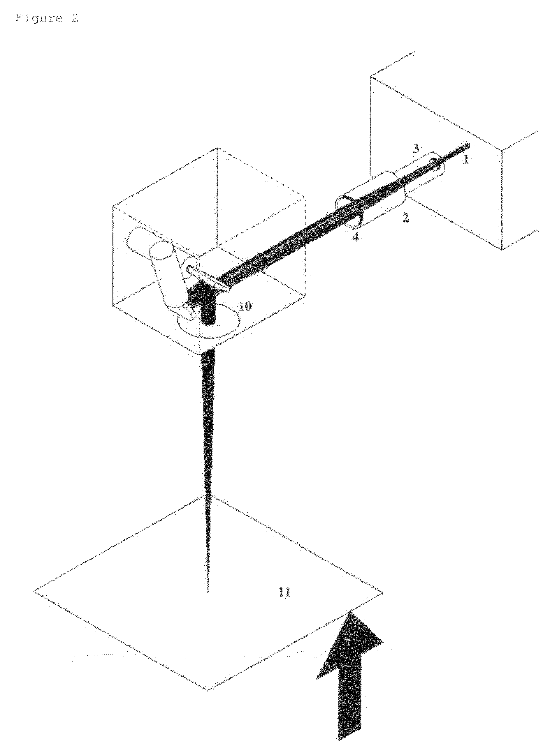
[0026]As depicted in FIG. 2, if said beam or laser beam (1) is converging entering ...


PUM


Abstract

This invention relates to a method of optical correction of field position distortions created by galvano motor scanning heads. In addition, the invention relates to the apparatus and method to achieve a calibration of said field positions to overcome said distortions generated by the delivery optics within a galvano motor scanning head using a pre-calibrated target that may be positioned into a registration or ‘lay’ system for ease of identifying and measuring said series of marks by removal and replacing said pre-calibrated target into said registration or ‘lay’ system, pre-determined logic means to generate a series of marks on said pre-calibrated target using said galvano motor scanning head and said galvano motor scanning head control apparatus and operator input so that said logic means may calculate from a minimum number of operator entries corresponding to said series of marks on said pre-calibrated target that may be positioned into said registration or ‘lay’ system for ease of identifying and measuring said series of marks by removal and replacing said pre-calibrated target into said registration or ‘lay’ system a full field correction of the field position distortions taking into account all beam or laser beam, mounting, alignment and parallelity intolerances to generate corrected galvano motor position control optical correction data reactive to the exact parameters of an individual laser, delivery optic/s, galvano motor scanning head and target plane set-up.

Description

FIELD OF THE INVENTION[0001]This invention relates to a method of optical correction of field position distortions created by galvano motor scanning heads. In addition, the invention relates to the apparatus and method to achieve a calibration of said field positions to overcome said distortions generated by the delivery optics within a galvano motor scanning head using a pre-calibrated target that may be positioned into a registration or ‘lay’ system for ease of identifying and measuring said series of marks by removal and replacing said pre-calibrated target into said registration or ‘lay’ system, pre-determined logic means to generate a series of marks on said pre-calibrated target using said galvano motor scanning head and said galvano motor scanning head control apparatus and operator input so that said logic means may calculate from a minimum number of operator entries corresponding to said series of marks on said pre-calibrated target that may be positioned into said registra...

Claims


Application Information

Patent Timeline
Patent Type & Authority Applications(United States)
IPC IPC(8): G02B26/10
CPCG02B27/0031G02B26/101
Inventor HASTINGS, STEPHENCOLES, STEPHEN
Owner ABARISCAN
Why Eureka
Try Eureka