Simple dispenser

A glue dispenser and simple technology, applied in the direction of coating, the device for coating liquid on the surface, etc., can solve the problems of inconvenient operation, prone to deviation, delayed work time, etc., to achieve easy dispensing operation and improve production. Efficiency, high product quality effect

Inactive Publication Date: 2010-06-30
深圳市耐迪科技有限公司
View PDF1 Cites 19 Cited by
  • Summary
  • Abstract
  • Description
  • Claims
  • Application Information

AI Technical Summary

Problems solved by technology

The glue dispensing machine with this structure can only dispens glue within a fixed range, the operation is not flexible enough, and the glue needs to be manually packed, which is easy to cause bubbles and deterioration of the glue
[0004] Existing manual dispensing machines usually use an air compressor as the air source, and the compressed air is delivered to the controller by the air compressor, and then the air pressure is adjusted by the controller to drive the piston in the barrel to make the glue flow from Extruding from the discharge nozzle, the traditional manual dispensing machine has the following defects: the traditional dispensing machine often needs to distribute the glue into the dispensing bottle, and the glue is easy to form bubbles and deteriorate in the dispensing bottle during the dispensing process , after the bubble bursts, it is easy to cause uneven dispensing thickness, which affects product quality. Moreover, the working time is delayed in the multiple packaging of raw materials, which affects production efficiency, and it is easy to cause material waste and environmental pollution.
There are also dispensers using fixed-dose rubber cartridges in the prior art, but usually because an external cylinder and cylinder piston are used to push the rubber cartridge sealing cover to move downward, in this structure, it is easy for the cylinder piston to push the rubber cartridge sealing cover. Offset occurs, resulting in the rupture of the rubber cartridge, and a bracket is required to fix the barrel or rubber cartridge, the structure is complex, and it is inconvenient to operate for a manual dispenser

Method used


Image

  • Simple dispenser
  • Simple dispenser
  • Simple dispenser

Examples


Embodiment Construction

[0030] The present invention will be described in further detail below in conjunction with accompanying drawing:

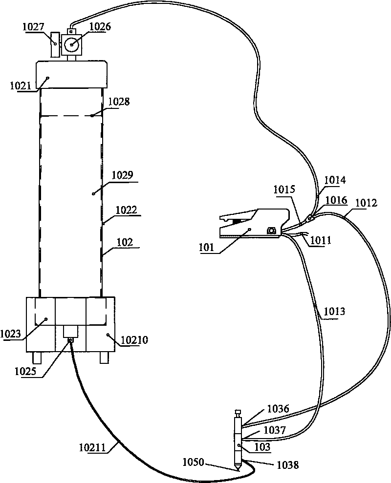
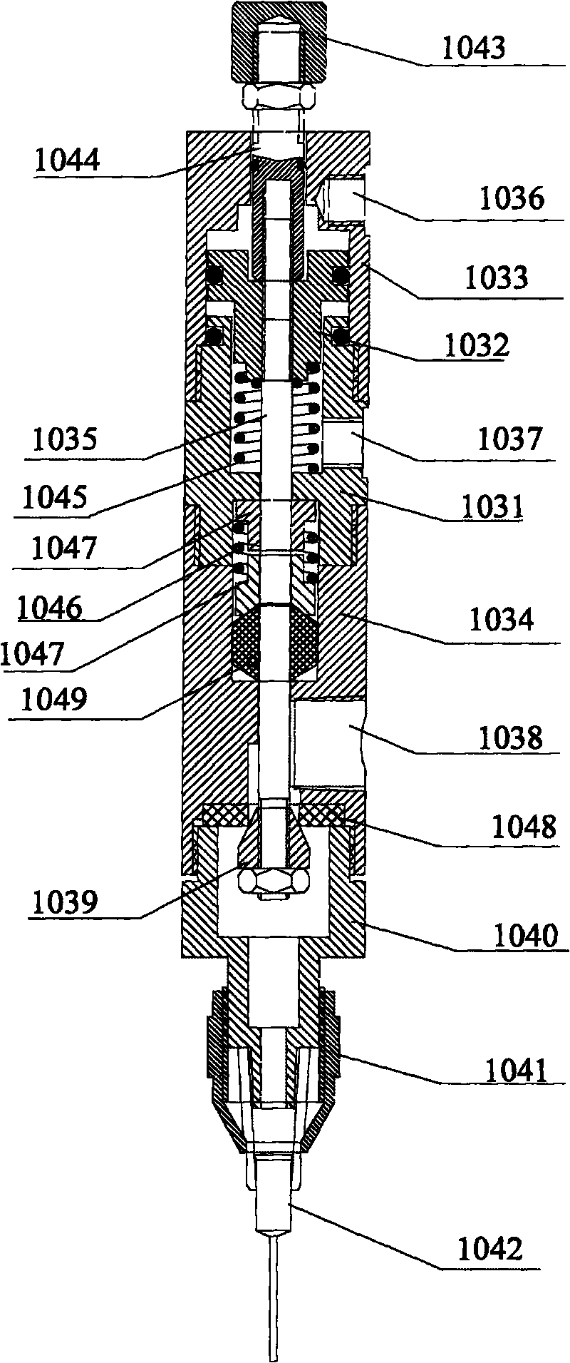
[0031] like figure 1 As shown, the simple dispensing machine provided by the present invention includes an air source, an air source controller 101, a closed barrel 102 that can accommodate glue, and a dispensing valve 103. The air source controller 101 includes an air inlet The first air outlet, the second air outlet, and the air inlet are connected to the air source through the first air pipe 1011 . In this embodiment, the air source is an air compressor, and the air source controller 101 is a foot valve that controls the opening and closing of the first air outlet and the second air outlet. like image 3 As shown, the main body of the dispensing valve 103 is cylindrical in shape. The dispensing valve 103 includes a cylinder, a piston 1032 disposed in the cylinder, a piston connecting rod 1035 connected to the piston 1032 and inserted in the cylinder, and a dr...


PUM


Abstract

The invention relates to a simple dispenser which comprises a gas source, a gas source controller, a material placing cylinder and a dispensing valve, wherein the gas source controller comprises a gas inlet and a gas outlet, the gas inlet is connected with the gas source through a gas pipe, and the gas outlet is respectively connected with the dispensing valve and the material placing cylinder; and the dispensing valve comprises a gas cylinder, a piston and a piston connecting rod, the dispensing valve is connected with a glue outlet of the material placing cylinder through a glue pipe, a glue cylinder containing the constant amount of a glue agent is sheathed in the material placing cylinder, and a sealing cover at the top part of the glue cylinder can move downward along the inner wall of the glue cylinder under the action of gas pressure of a cavity at the top part of the material placing cylinder. The simple dispenser adopts the glue cylinder with the constant dosage and can avoid the cumbersome operation of repeatedly sub-packaging the glue agent into a dispensing bottle and the problems of waste of the glue agent, environmental pollution, bubbles, deterioration and other problems during the sub-packaging process, be energy-saving and environment-friendly, and simultaneously avoid the problem of rupture of the glue cylinder caused by deviation of the piston of the gas cylinder when adopting an external gas cylinder; and movable and fixed seats are arranged at the bottom part of the material placing cylinder, the structure is simple, the dispensing valve is light and simple, the opening and the closing of the dispensing valve are controlled through a pedal valve, and the operation is convenient.

Description

technical field [0001] The invention relates to a simple glue dispenser. Background technique [0002] Existing dispensing machines are widely used in the dispensing of industries such as electronics, electrical appliances, communication equipment, automobile industry, medical industry, mobile phone industry, toys, glasses, clocks and watches. With the continuous progress of society, people's requirements for product quality are getting higher and higher, especially in the enhancement of the internal structure of the product and the protection of the appearance. The existing technology usually uses various adhesives (such as ultraviolet glue, instant glue, etc.) to bond various materials to each other, and glue is used for sealing, fixing, coating, filling, etc. in various industries to strengthen the internal and external structure of the product. [0003] The patent No. 200820034654.6 discloses a dispensing machine, including: workbench, frame, dispensing valve, cylinder,...

Claims


Application Information

Patent Timeline
Patent Type & Authority Applications(China)
IPC IPC(8): B05C5/02B05C11/00B05C11/10B05C11/11
Inventor 钟若谷
Owner 深圳市耐迪科技有限公司
Why Eureka
Try Eureka