Supercharge Your Innovation With Domain-Expert AI Agents!

Thermal interface material and using method thereof

一种热界面材料、热源的技术,应用在传热改性、热交换设备、半导体/固态器件零部件等方向,能够解决导热颗粒难以熔融、导热系数下降、影响热界面材料导热系数等问题,达到降低界面热阻、优异导热性能的效果

Active Publication Date: 2010-06-30
TSINGHUA UNIV +1
View PDF7 Cites 10 Cited by
  • Summary
  • Abstract
  • Description
  • Claims
  • Application Information

AI Technical Summary

Problems solved by technology

However, the first heat-conducting particles with a low melting point are in a molten state during operation, and their own thermal conductivity will drop significantly, thereby affecting the thermal conductivity of the thermal interface material; in addition, most heat-conducting particles with high thermal conductivity will not work at the operating temperature of the heat source. It is difficult to melt, such as the melting point of silver, aluminum, copper, etc. with excellent thermal conductivity are above 350 ° C, while the operating temperature of most heat sources is below 350 ° C, such as the operating temperature of the CPU below 120 ° C, which makes the first heat conduction Particle selection is very limited

Method used


Image

  • Thermal interface material and using method thereof
  • Thermal interface material and using method thereof
  • Thermal interface material and using method thereof

Examples


Embodiment Construction

[0016] The thermal interface material and the method of using the thermal interface material according to the embodiment of the present invention will be further described in detail below with reference to the accompanying drawings.

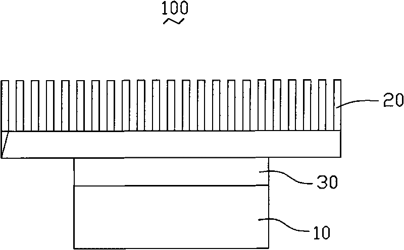
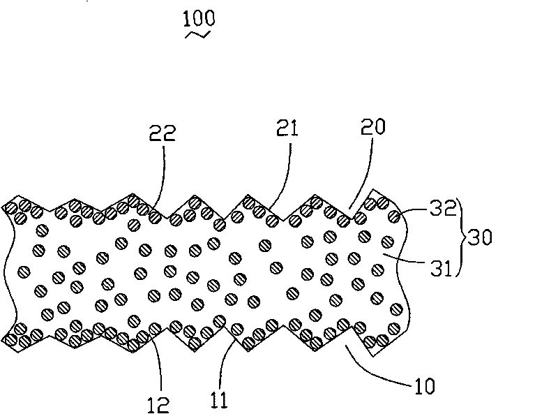
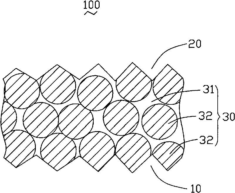
[0017] see figure 1 and figure 2 , is a schematic diagram of the application of the thermal interface material 30 provided by the first embodiment of the present invention. During practical application, the thermal interface material 30 is disposed between a heat source 10 and a heat dissipation device 20 for transferring heat from the heat source 10 to the heat dissipation device 20 . The heat source 10 , the heat sink 20 and the thermal interface material 30 together form an electronic device 100 .

[0018] The heat source 10 may be a semiconductor integrated device, or an IC circuit, a resistor or other heating elements. The heat source 10 has a protection temperature T1 that prevents the heat source 10 from being damaged by overheating. ...


PUM

PropertyMeasurementUnit
particle diameteraaaaaaaaaa
melting pointaaaaaaaaaa

Abstract

The invention relates to a thermal interface material used for transferring heat on a heat source to a radiating device. The heat source has a protective temperature for preventing the heat source from being damage due to overheating, and the thermal interface material is located between the heat source and the radiating device. The thermal interface material includes a flexible matrix and at least one first heat conduction granule filled in the flexible matrix, wherein the grain diameter of the first heat conduction granule before melting is smaller than 100nm and the melting point is lower than the protective temperature; the grain diameter of the first heat conduction granule after melting is larger than 100nm and the melting point is higher than the protective temperature. The invention also relates to a using method of the thermal interface material.

Description

technical field [0001] The invention relates to a thermal interface material and a method for using the thermal interface material. Background technique [0002] In recent years, with the rapid development of the integration process of semiconductor devices, the degree of integration of semiconductor devices has become higher and higher, and the volume of devices has become smaller and smaller. However, the reduction in the volume of semiconductor devices has also increased its requirements for heat dissipation. In order to meet the heat dissipation requirements of the semiconductor devices, various heat dissipation methods such as fan heat dissipation, water-cooled auxiliary heat dissipation, and heat pipe heat dissipation are widely used, and certain heat dissipation effects have been achieved. However, because the contact interface between the heat sink and the heat source (semiconductor integrated device, such as CPU) is uneven, the actual contact area is generally less ...

Claims


Application Information

Patent Timeline
Patent Type & Authority Applications(China)
IPC IPC(8): C08L101/00C08K3/08C08K7/24C08K7/06H01L23/373H01L21/50
CPCH01L23/3737F28F2013/006H01L23/42H01L24/29H01L24/83H01L2224/2929H01L2224/293H01L2224/29499H01L2224/32245H01L2224/83365H01L2224/83385H01L2224/8385H01L2924/14H01L2924/0665H01L2924/00
Inventor 汪友森姚湲戴风伟王继存张慧玲
Owner TSINGHUA UNIV
Features
  • R&D
  • Intellectual Property
  • Life Sciences
  • Materials
  • Tech Scout
  • Unparalleled Data Quality
  • Higher Quality Content
  • 60% Fewer Hallucinations
Learn More