Wheel valve

A wheel and valve body technology, applied in the field of wheel valves, to achieve the effects of accurate pressure measurement, fast inflation and deflation, and simple structure

Inactive Publication Date: 2010-06-30
刘艳昭
View PDF4 Cites 7 Cited by
  • Summary
  • Abstract
  • Description
  • Claims
  • Application Information

AI Technical Summary

Problems solved by technology

However, such a sealing structure has a correlation between the sealing ability of the gas and the size of the gas pressure, and the sealing ability may be reduced at low pressure, that is to say, the rotating sealing chamber may leak during the deflation process. This requires that the gas in the tire air chamber can return to the sealed air chamber to compensate for the lost gas

Method used


Image

  • Wheel valve
  • Wheel valve

Examples


Embodiment Construction

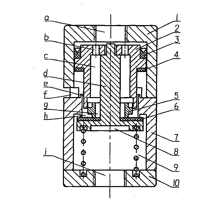
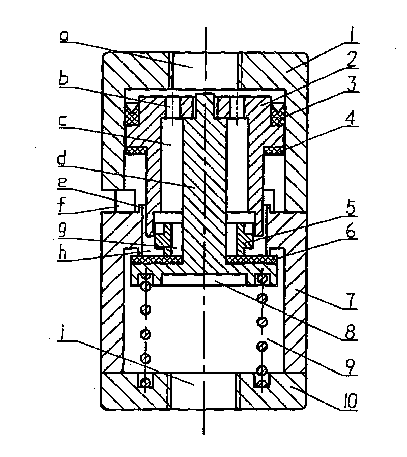
[0024] A wheel valve, consisting of an upper valve body (1), a control spool (2), a lip seal (3), a one-way throttle spool (5), a lower valve body (7), a main spool (8 ), spring (9), and valve bottom (10), the control spool (2) is installed in the inner cavity of the upper valve body (1), and the outer wall of the control spool (2) and the inner wall of the upper valve body (1) The gap is sealed by the lip seal (3) installed on the control spool (2), and the lower port of the control spool (2) extends into the main valve port (h) on the lower valve body (7), with The main spool (8) with the axial push rod (d) is installed in the inner chamber of the lower valve body (7), and the necked free end of the push rod (d) passes through the main valve port (h) and the axial direction of the control spool. The hole (c) extends into the central hole on the top of the control spool (2), and the one-way throttle spool (5) sleeved on the push rod (d) is located at the expansion of the lowe...


PUM


Abstract

The invention discloses a wheel valve in an inflating and deflating system, which comprises an upper valve body (1), a control valve core (2), a lip-shaped seal ring (3), a one-way throttling valve core (5), a lower valve body (7), a main valve core (8), a spring (9) and a valve bottom (10), wherein the control valve core (2) is installed at an inner cavity of the upper valve body (1); the main valve core (8) with an axial push rod (d) is installed at an inner cavity of the lower valve body (7); the neck shrinking free end of the push rod (d) extends into a center hole of the top of the control valve core (2) after penetrating through a main valve opening (h) and a control valve core axial hole (c); the one-way throttling valve core (5) sleeved on the push rod (d) is positioned at the flared position of the lower end of the control valve core axial hole (c); a return spring (9) is positioned between the main valve core (8) and the valve bottom (10); and a throttling air gap is arranged between axial holes of the one-way throttling valve core (5) and the control valve core (2). The invention has simple structure, high reliability, wheel edge exhaust and accurate pressure measurement by adopting the floating type one-way throttling valve core, can monitor tire pressure in real time and realize the simultaneous pressure measurement of a single axle or a complete axle and is beneficial to simplifying a control system and a gas circuit structure.

Description

technical field [0001] The invention relates to a valve for inflation and deflation of rotating tires, in particular to a wheel valve in a tire central inflation and deflation system. Background technique [0002] The tire central inflation and deflation system (CTI / DS) of off-road vehicles is mainly composed of air source, electronic control unit, rotating sealed air chamber, wheel valve and other parts, which are used to adjust the air pressure of the tire to adapt to different road conditions, thereby improving the tire pressure. mobility of the vehicle. The wheel valve is one of the key components of the system. It is installed on the wheel and rotates with the wheel. CTI / DS performs operations such as inflation, deflation, pressure measurement and pressure maintenance of the tire through this valve. [0003] The structure, function and working characteristics of the wheel valve not only determine its own size, but also determine the speed of system inflation and defla...

Claims


Application Information

Patent Timeline
Patent Type & Authority Applications(China)
IPC IPC(8): F16K15/20
Inventor 刘艳昭
Owner 刘艳昭
Why Eureka
Try Eureka