
Vehicle headlamp

一种前照灯、车辆的技术,应用在车辆照明系统、车头灯、车辆部件等方向,能够解决不均组合的误差等问题,达到部件件数少、提高组装精度、成本降低的效果

Inactive Publication Date: 2010-06-30
ICHIKOH IND LTD
View PDF1 Cites 21 Cited by
  • Summary
  • Abstract
  • Description
  • Claims
  • Application Information

AI Technical Summary

Problems solved by technology

Therefore, in the existing vehicle headlamp, an uneven combination error occurs on the projection lens and the shielding member of the two constituent parts of the optical element, and the assembly accuracy of the projection lens and the shielding member of the two constituent parts of the optical element is affected. There is a problem with

Method used


Image

  • Vehicle headlamp
  • Vehicle headlamp
  • Vehicle headlamp

Examples


Embodiment

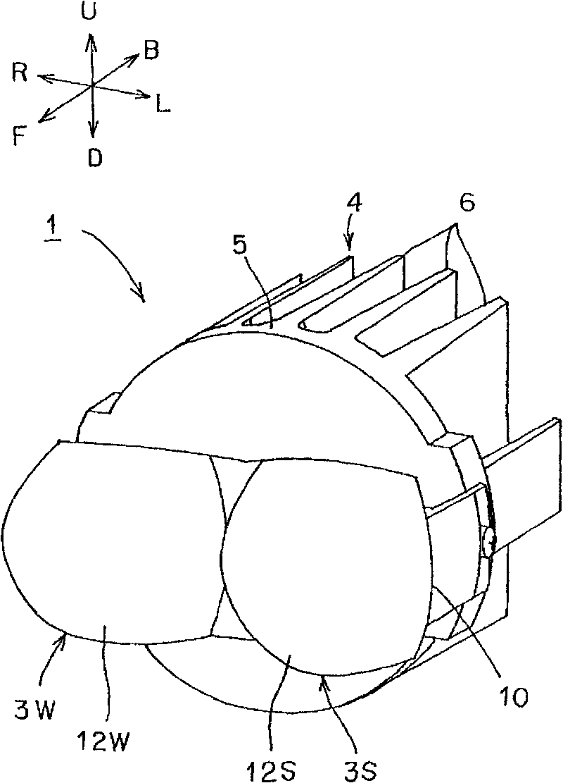
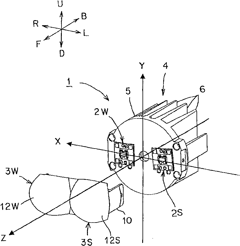
[0059] Hereinafter, the structure of the vehicle headlamp of this embodiment will be described. In the figure, reference numeral 1 is a vehicle headlamp (automobile headlamp) in this embodiment. The vehicle headlamp 1 described above is a vehicle headlamp for a left-hand traffic lane. Furthermore, the vehicle headlamp for the right-hand traffic lane is reversed in the structure and the like of the above-mentioned vehicle headlamp 1 for the left-hand traffic lane. In addition, in figure 2 Among them, X, Y, and Z form a Cartesian coordinate system (X-Y-Z Cartesian coordinate system). The X-axis is the horizontal axis in the left-right direction, and the opposite lane side, that is, the right side R in this embodiment is the + direction, and the left side L is the - direction. Furthermore, the Y-axis is a vertical axis in the up-down direction, and in this embodiment, the upper side U is the + direction, and the lower side D is the - direction. In addition, the Z-axis is an ...


PUM


Abstract

A vehicle headlamp has semiconductor-type light sources and lenses. Emission surfaces of the lenses are made of free curved faces controlled to be curved so that: projection images of light emitting chips of the semiconductor-type light sources, which is emitted from the emission surfaces, are not convexly curved in an upward direction from cutoff lines on a screen light distribution of a light distribution pattern for low beam. As a result, the vehicle headlamp can achieve downsizing, weight reduction, and cost reduction. In addition, the precision of assembling an optical element can be improved.

Description

technical field [0001] The present invention relates to a vehicle headlamp that uses a semiconductor-type light source as a light source and irradiates a light distribution pattern having a cutoff line, for example, a light distribution pattern for low beam (light distribution pattern for anti-glare) toward the front of a vehicle. Background technique [0002] Such a vehicle headlamp is conventionally known (for example, Patent Document 1: Japanese Patent No. 4182126). Hereinafter, a conventional vehicle headlamp will be described. A conventional vehicle headlamp includes an LED light source, a projection lens, and a shielding member. Hereinafter, the operation of a conventional vehicle headlamp will be described. When the LED light source is turned on, part of the light from the LED light source is shielded by the shielding member, and the light shielded by the shielding member is irradiated (projected) forward of the vehicle as a light distribution pattern having a cutof...

Claims


Application Information

Patent Timeline
Patent Type & Authority Applications(China)
IPC IPC(8): F21S8/10F21V5/04F21V11/00F21Y101/02F21W101/10
CPCF21S48/1258G02B19/0061G02B27/0916G02B19/0014F21Y2101/02F21S48/1275F21S48/1154F21Y2115/10F21S41/143F21S41/151F21S41/255F21S41/265
Inventor 大久保泰宏
Owner ICHIKOH IND LTD
Learn More