On-line cleaning and de-dusting element of heat exchange tube with directional tail wing

A heat exchange tube and tail fin technology is applied in the field of on-line cleaning and descaling elements of heat exchange tubes, which can solve the problems of clogging and cleaning effect, horizontal blocking of heat exchange tubes, and inability to control movement.

Inactive Publication Date: 2011-06-29
TSINGHUA UNIV
View PDF1 Cites 0 Cited by
  • Summary
  • Abstract
  • Description
  • Claims
  • Application Information

AI Technical Summary

Problems solved by technology

The structural features disclosed in this patent document partially overcome the above-mentioned deficiencies, but there are still the following problems: 1. For rubber balls with a spherical structure with helical fins, the direction of movement of the minimum flow resistance is not the direction of the designed rotation axis, The test shows that its axis of rotation is generally perpendicular to the axis of rotation of the design, that is, generally in the heat exchange tube, it is a translation or rolling across the heat exchange tube, and the direction deviating from the axis of rotation of the design may cause clogging or poor cleaning effect , although it is mentioned that "in order to make the spherical rubber ball move better in the direction set in the heat exchange tube, it is also possible to install a tail rope to control the direction on the surface of the spherical rubber ball.
", but did not disclose its details. Experiments show that the "tail rope" structure can not control the movement in the direction of the set rotation axis.
2. For rubber balls with an ellipsoidal structure, although they can be guaranteed to move in the set direction in the heat exchange tube, they are particularly prone to the problem of cross-blocking at the end of the heat exchange tube.

Method used


Image

  • On-line cleaning and de-dusting element of heat exchange tube with directional tail wing
  • On-line cleaning and de-dusting element of heat exchange tube with directional tail wing
  • On-line cleaning and de-dusting element of heat exchange tube with directional tail wing

Examples


Embodiment 1

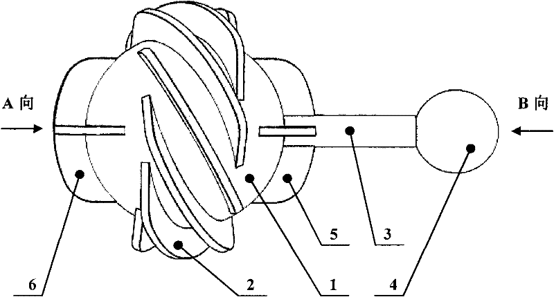
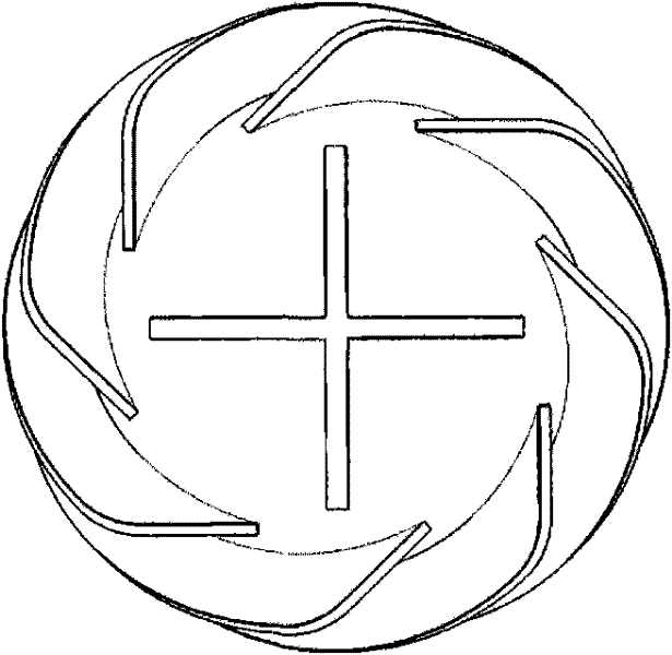
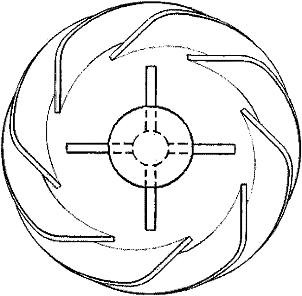
[0023] Such as figure 1 As shown, the present invention includes a solid rubber ball 1, a plurality of inclined fins 2 uniformly arranged on the surface of the ball, a directional tail post 3, a small ball 4, crossed front wings 6 and rear wings 5. The tail ball 4 that the directional tail post 3 and the tail post end are connected forms the directional tail fin. figure 2 It is a schematic diagram of Embodiment 1 of the present invention in direction A. image 3 It is a schematic diagram of Embodiment 1 B of the present invention. Figure 4 It is a schematic diagram of the working principle of Embodiment 1 of the present invention, and 7 in the figure is the inside of the heat exchange tube to be cleaned. Figure 5 It is a schematic diagram of the working principle of the cleaning ball without tail fins. As a comparison with the working principle of the present invention, 7 is in the heat exchange tube to be cleaned, and 8 is a cleaning ball without tail fins.

[0024] In ...

Embodiment 2

[0032] Such as Figure 6 As shown, the difference between this embodiment and Embodiment 1 is that the directional tail is composed of a cylinder and a plurality of fins (tail fins) arranged at the tail of the cylinder. Replacing the tail ball with the tail fin can further enhance the cleaning and descaling effect of the tail fin, but the disadvantage is that it is easy to wear.

Embodiment 3

[0034] Such as Figure 7 As shown, the difference between this embodiment and Embodiment 1 is: the directional tail is made up of a column (tail post), and its structure is simpler.


PUM


Abstract

The invention discloses an on-line cleaning and de-dusting element of a heat exchange tube with a directional wing, which belongs to technical field of on-line cleaning and de-dusting; the characteristics are as follows: the element comprises: a solid rubber ball, a plurality of tilt wings or spiral wings, a plurality of flow-blocking wings and a directional tail wing, wherein, the plurality of tilt wings are evenly arranged at the surface of the solid rubber ball at the circumferential direction, the largest outline of the tilt wings is in a ball shape, meanwhile, the directional tail wing and the flow-blocking wings presenting a crisscross shape are connected to the surface of the solid rubber ball, the connection location is the junction of a rotating shaft of the solid rubber ball where the plurality of tilt wings are evenly arranged along the circumferential direction and the spherical surface of the solid rubber ball, and the largest outline of the flow-blocking wings is in a ball shape. The cleaning and de-dusting element with the directional tail wing provided by the invention moves forward along with the fluid body and simultaneously generates rotation under the effect ofthe fluid body in the heat exchange tube, and has advantages of good cleaning and de-dusting effect and being not easy to block the heat exchange tube.

Description

technical field [0001] The invention relates to an on-line cleaning and descaling element of a heat exchange tube with a directional fin. Background technique [0002] Shell-and-tube heat exchangers are widely used in electric power, chemical industry, petroleum and other industrial fields. Most of the heat exchangers have fouling and scaling during operation, especially the condensers cooled by circulating water. , water cooler, etc. The fouling and scaling of the heat exchanger will reduce the heat transfer coefficient of the equipment, increase the energy consumption, and even cause the equipment to fail to operate normally due to pipe blockage; scaling will also form corrosion under the scale and shorten the service life of the equipment. At present, there are online and off-line methods for cleaning and descaling in the heat exchange tubes of shell-and-tube heat exchangers. Online cleaning and descaling has unique advantages because it does not affect the normal produc...

Claims


Application Information

Patent Timeline
Patent Type & Authority Patents(China)
IPC IPC(8): F28G1/12
Inventor 孟继安
Owner TSINGHUA UNIV
Why Eureka
Try Eureka