

Overvoltage comparison circuit
A technology of comparing circuits and overvoltages, applied in the measurement of electrical variables, current/voltage, measurement devices, etc., can solve the problems of not meeting the needs of use, wasting chip area, etc., and achieve the effect of reducing consumption area and manufacturing cost.
- Summary
- Abstract
- Description
- Claims
- Application Information
AI Technical Summary
Problems solved by technology
Method used
Image

Examples
Embodiment Construction
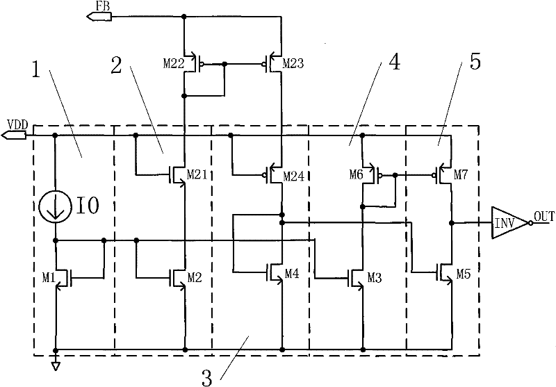
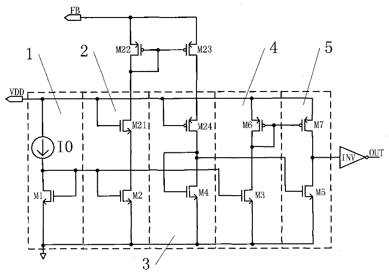
[0016] Such as figure 2 As shown, the present invention, that is, an overvoltage comparison circuit, includes an inverter INV and first to fifth branches 1 to 5 respectively connected in parallel between an external power supply VDD and ground, wherein:
[0017] The first branch 1 includes a current source I0 and a first low-voltage device M1 connected in series, and the gate of the first low-voltage device M1 is connected to the drain, and its source is grounded;
[0018] The second branch circuit 2 includes a first high-voltage device M21 and a second low-voltage device M2 connected in series, wherein the source of the second low-voltage device M2 is grounded, its gate is connected to the gate of the first low-voltage device M1, and the first high-voltage device M2 The gate of the device M21 is connected to the external power supply VDD, and a second high-voltage device M22 is connected in series between its drain and an external signal source FB to be tested. The source of...
PUM
 Abstract
Description
Claims
Application Information