
Rotatable scanning head

A technology of rotating scanning and scanning head, used in instruments, character and pattern recognition, computer parts and other directions, can solve the problems of complex structure, many parts, and insufficient positioning, and achieve easy implementation, simple structure, and reduce work fatigue. Effect

Inactive Publication Date: 2010-06-30
深圳奥士达电子有限公司 +1
View PDF0 Cites 2 Cited by
  • Summary
  • Abstract
  • Description
  • Claims
  • Application Information

AI Technical Summary

Problems solved by technology

However, since the existing rotatable scanning head uses a cam to locate the rotation angle, the positioning is usually not firm enough, which easily leads to the situation that the rotated scanning head turns to the original angle direction, and the cam is used for positioning. More parts are required and the structure is more complicated

Method used


Image

  • Rotatable scanning head
  • Rotatable scanning head
  • Rotatable scanning head

Examples


Embodiment Construction

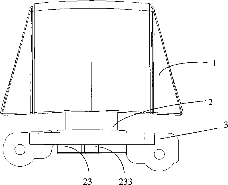
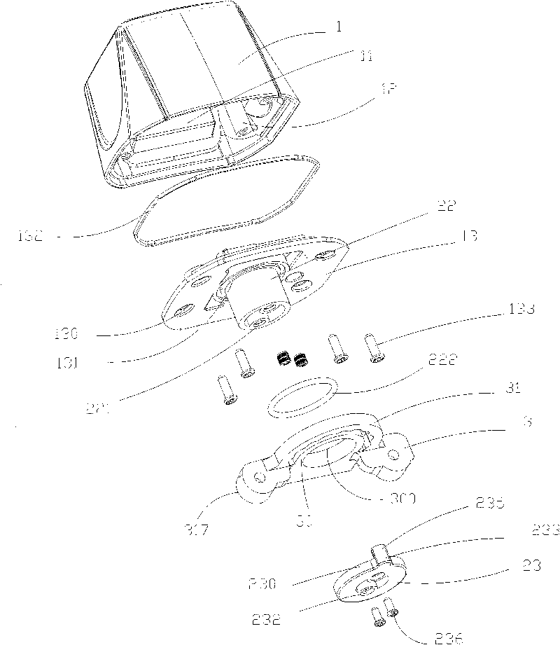
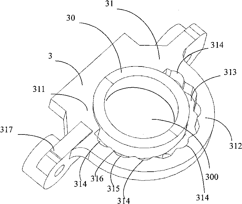
[0024] Please refer to figure 1 and figure 2 , which are respectively a combined schematic view and a three-dimensional exploded view of a preferred embodiment of the rotatable scanning head of the present invention. The rotatable scanning head is used for a hand-held scanning machine to read data, and includes a scanning head body 1 , a rotating part 2 and a positioning part 3 .

[0025] The scanning head body 1 is roughly trapezoidal, and there is an accommodating space therein, in which the scanning head electronic circuit 11 is accommodated. The scanning window (not shown) is arranged on the front side of the body 1 for aligning the target to be scanned. For data reading, of course, it can also be arranged on the top surface of the main body 1, etc. The bottom of the body 1 is open, and a plurality of connecting columns 12 are arranged on the inner wall. The connecting columns 12 extend from the top of the body 1 toward the bottom opening and are provided with threads. ...


PUM


Abstract

The invention relates to a rotatable scanning head which comprises a scanning head body, a rotating part and a positioning part, wherein the interior of the scanning head body is provided with an accommodating space so as to accommodate an electronic circuit of the scanning head; one surface of the scanning head body is provided with a scanning window; the rotating part is fixed and connected with the scanning head body and is provided with a first positioning part; the positioning part is provided with a second through hole and a second positioning part; the rotating part is rotatably perforated in the second through hole between at least two rotating positions and is respectively positioned on the at least two rotating positions of the positioning part by the coordination between the first positioning part and the second positioning part of the positioning part. The rotatable scanning head can be rotatably and firmly positioned at the require angle, has simple structure and is easy to be realized.

Description

technical field [0001] The present invention relates to a scanning device, in particular to a rotatable scanning head which can be rotated and positioned to a specific angle. Background technique [0002] In today's life, as the third largest computer input device after the mouse and keyboard, the scanning device can not only quickly realize a large amount of text entry, computer-aided design, document production, and graphic database management, but also can record various information in a realistic and real-time manner. image. Scanning equipment can convert various documents, photos, slides, negatives and other manuscripts through a series of optical and electrical conversions, and finally form digital signals that can be recognized by computers. Composition of digital image files for computer storage, display, modification, and improvement to meet people's needs in various forms, so scanning equipment is playing an increasingly important role in human life. [0003] As ...

Claims


Application Information

Patent Timeline
Patent Type & Authority Applications(China)
IPC IPC(8): G06K9/24
Inventor 刘立新胡俊睿黄潇凌
Owner 深圳奥士达电子有限公司
Learn More