Liquid-crystal display device

A technology of liquid crystal display and display screen, applied in static indicators, instruments, etc., can solve problems such as consumption and multi-energy

Inactive Publication Date: 2010-06-30
AU OPTRONICS CORP
View PDF0 Cites 9 Cited by
  • Summary
  • Abstract
  • Description
  • Claims
  • Application Information

AI Technical Summary

Problems solved by technology

If the liquid crystal display device 500 is driven by dot inversion, the polarity of the data driving signal output to each pixel unit needs to be reversed, so more energy will be consumed

Method used


Image

  • Liquid-crystal display device
  • Liquid-crystal display device
  • Liquid-crystal display device

Examples


Embodiment Construction

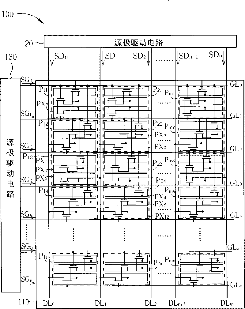
[0024] Please refer to image 3 , image 3 It is a schematic diagram of a liquid crystal display device 100 in the first embodiment of the present invention. The liquid crystal display device 100 includes a liquid crystal display panel 110 , a source driving circuit 120 , and a gate driving circuit 130 . The liquid crystal display panel 110 is provided with a plurality of parallel data lines DL 0 ~DL m , multiple parallel gate lines GL 0 ~GL n , and a pixel matrix. The pixel matrix contains multiple pixel units P 11 ~P mn (m and n are positive integers), each pixel unit includes a red pixel, a green pixel and a blue pixel. Each pixel includes a thin film transistor (thin film transistor, TFT) switch vertically disposed at the intersection of the corresponding data line and the gate line. For example, pixel unit P 13 Contains red pixel PX1, green pixel PX5 and blue pixel PX9, and the pixel unit P 24 Contains red pixel PX4, green pixel PX8 and blue pixel PX12.

[002...


PUM


Abstract

The invention discloses a liquid-crystal display device, comprising a liquid-crystal display panel, a source electrode drive circuit and a gate drive circuit. The liquid-crystal display panel is provided with a pixel module in OTGD and Z-shaped layout, so the channel number of the gate drive circuit can be reduced under same resolution, a display effect of three-point reversion or point inversioncan be reached in a line reversion drive method with low energy consumption, and at the same time a TDP framework can be realized to achieve a narrow-border effect.

Description

technical field [0001] The invention relates to a liquid crystal display device, in particular to a liquid crystal display device which adopts OTGD (one-three gated driving) and a zigzag layout to achieve dot inversion and narrow frame effects. Background technique [0002] Liquid crystal display (liquid crystal display, LCD) has the advantages of low radiation, small size and low energy consumption, and has gradually replaced the traditional cathode ray tube (cathode ray tube, CRT) display, and is widely used in notebook computers, personal Information products such as digital assistants (personal digital assistant, PDA), flat-screen TVs, or mobile phones. [0003] Please refer to figure 1 , figure 1 It is a schematic diagram of a liquid crystal display device 500 in the prior art. The liquid crystal display device 500 includes a liquid crystal display panel 510 , a source driving circuit 520 , and a gate driving circuit 530 . The liquid crystal display panel 510 is pro...

Claims


Application Information

Patent Timeline
Patent Type & Authority Applications(China)
IPC IPC(8): G09G3/36
Inventor 田沛霖陈耿铭洪集茂
Owner AU OPTRONICS CORP
Why Eureka
Try Eureka