
Switching mode power supply

A switching stabilized power supply and power supply technology, which is applied in the direction of irreversible AC power input conversion to DC power output, etc., can solve the problems of limited application range, bulky and bulky ordinary silicon iron core transformer, etc., and achieve wide input voltage range and production debugging. Convenience, low impact effect

Inactive Publication Date: 2010-06-30
SOUTHWEST JIAOTONG UNIV
View PDF1 Cites 3 Cited by
  • Summary
  • Abstract
  • Description
  • Claims
  • Application Information

AI Technical Summary

Problems solved by technology

Although individual thyristor regulated power supplies have achieved some simplification of the circuit, they are not suitable for occasions where the input power supply voltage and the output regulated DC voltage value differ greatly (such as when the input 220V power supply outputs 12V regulated DC voltage); when the input voltage When there is a large difference from the output regulated DC voltage value, it must be used with a bulky and bulky ordinary silicon-iron core transformer, which severely limits its application range

Method used


Image

  • Switching mode power supply
  • Switching mode power supply

Examples


specific Embodiment approach

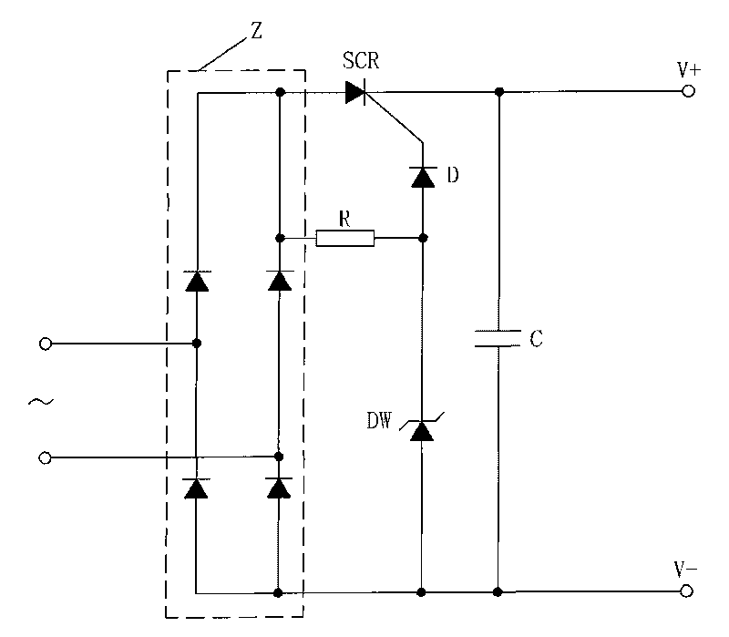
[0019] figure 1 Shown, a specific embodiment of the present invention is: a switching regulator power supply, its composition is:

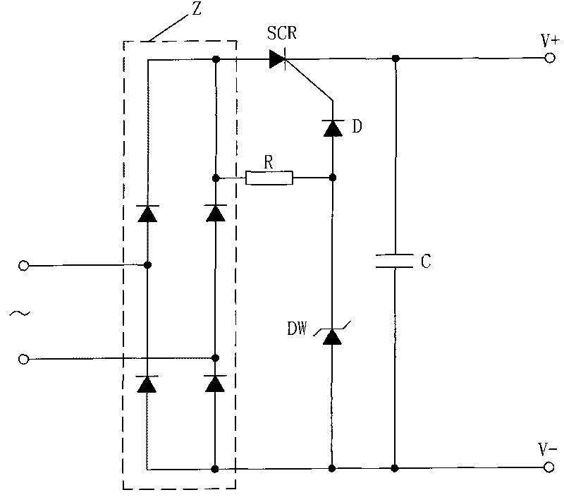
[0020] The two input terminals of the bridge rectifier circuit Z are connected to the AC power supply; the positive output terminal of the bridge rectifier circuit Z is connected to the anode of the one-way thyristor SCR, and the cathode of the one-way thyristor SCR is the positive output terminal V+ of the power supply; The negative output terminal of the bridge rectifier circuit Z is the negative output terminal V- of the power supply, and the filter capacitor C is connected in parallel between the positive and negative output terminals V+ and V- of the power supply;

[0021] The control pole of the one-way thyristor SCR is connected to the negative terminal of the voltage regulator DW, and the positive terminal of the voltage regulator DW is connected to the negative output terminal V- of the power supply; the current limiting resistor R is con...


PUM


Abstract

The invention provides a switching mode power supply. In the power supply, two input ends of a bridge rectifier (Z) are connected with an alternating current power supply; the positive input end of the bridge rectifier (Z) is connected with an unidirection silicon controlled rectifier (SCR); a cathode of the unidirection silicon controlled rectifier (SCR) is the positive output end (V+) of a power supply; the negative output end of the bridge rectifier (Z) is the negative output end (V-) of the power supply; a filter capacitor (C) is connected in parallel between the positive output end (V+) and the negative output end (V-) of the power supply; a control electrode of the unidirection silicon controlled rectifier (SCR) is connected with the negative end of a voltage-regulator tube (DW); the positive end of the voltage-regulator tube (DW) is connected with the negative output end (V-) of the power supply; and a current limit resistor (R) is connected between the positive output end of the bridge rectifier (Z) and the negative end of the voltage-regulator tube (DW). The power supply has the advantages of low cost, high efficiency, small volume, convenient production and debugging, wide input voltage range and no high-frequency high-voltage pulse radiation, and is particularly applicable to driving power supply of various semiconductor lamps.

Description

technical field [0001] The invention relates to a switching stabilized voltage power supply. Background technique [0002] The existing switching regulated power supplies are complex, high in cost, large in size, demanding in production conditions, poor in versatility, and have strong pulse interference. For example, the commonly used positive and flyback switching regulated power supplies contain inductance components, so there is magnetic flux leakage in the circuit, and the high-voltage pulse impact generated by it will cause impact on the drive circuit and semiconductor light-emitting components, and cause switching tubes and other components Problems such as too high electrical stress of the device will significantly shorten the life and reliability of electrical appliances, and are especially not suitable for power supplies for semiconductor light-emitting diode lamps. Although there are stabilized power supplies using silicon controlled rectifiers without inductive c...

Claims


Application Information

Patent Timeline
Patent Type & Authority Applications(China)
IPC IPC(8): H02M7/12
Inventor 苟先太
Owner SOUTHWEST JIAOTONG UNIV
Learn More