
LED lamp and drive circuit

A technology of LED lamps and driving circuits, which is applied in the field of lighting, and can solve problems such as unfavorable business and office work, and few driving circuits with built-in emergency functions.

Inactive Publication Date: 2010-06-30
OCEANS KING LIGHTING SCI&TECH CO LTD +1
View PDF7 Cites 30 Cited by
  • Summary
  • Abstract
  • Description
  • Claims
  • Application Information

AI Technical Summary

Problems solved by technology

[0002] At present, in terms of household or commercial lamps, incandescent lamps or fluorescent lamps are generally used. From the perspective of energy saving, environmental protection and service life, there are problems with the environment and economy. However, the use of low power (mainly 8W or less) LED lamps can greatly improve these problems, but the existing drive circuits using this kind of LED lamps rarely have their own emergency functions. From the perspective of frequent power outages, it will bring many disadvantages to the environment and economy. , is also not conducive to the smooth development of business and office work

Method used


Image

  • LED lamp and drive circuit
  • LED lamp and drive circuit
  • LED lamp and drive circuit

Examples


Embodiment Construction

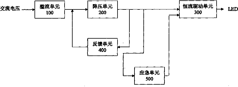
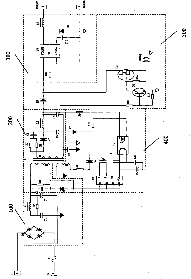
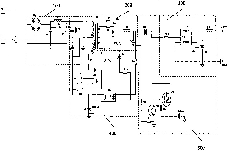
[0010] Such as figure 1 As shown, in the logic structure diagram of Embodiment 1 of the LED lamp driving circuit of the present invention, the LED lamp driving circuit includes a rectifier unit 100, a step-down unit 200, a constant current drive unit 300, a feedback unit 400, and an emergency unit 500 , Wherein the input terminal of the rectifier unit 100 is connected to AC power, and is used to convert the input AC voltage into a DC voltage; the input terminal of the step-down unit 200 is connected to the output terminal of the rectifier unit 100, and is used to output the direct current from the rectifier unit 100 The voltage is stepped down; the input end of the constant current drive unit 300 is connected to the output end of the step-down unit 200, and the output end of the constant current drive unit 300 is connected to the LED, which is used to implement the LED lamp using the DC voltage output by the step-down unit 200 Constant current drive provides a stable DC voltage ...


PUM


Abstract

The present invention relates to an LED lamp and a drive circuit thereof, wherein, the drive circuit comprises a rectifying unit, a voltage reduction unit, constant-current drive unit and an emergency unit. In the emergency unit, the base electrode of a triode is connected with the output of the voltage reduction unit through a first divider resistance while the emitter of the triode is grounded;a second divider resistance is connected between the base electrode and the emitter of the triode; the collector electrode of the triode is connected with the grid electrode of an MOS tube; the source electrode of the MOS tube is connected with the output of an emergency power supply while the drain electrode is connected with the power input of the constant-current drive unit; a pull-up resistoris connected between the grid electrode and the source electrode of the MOS tube; and the positive electrode of a blocking diode is connected with the output of the voltage reduction unit while the negative electrode is connected with the power input of the constant-current drive unit. The present invention can guarantee that the constant-current drive unit can output current for driving LEDs to work and light normally even though alternate current fails.

Description

Technical field [0001] The present invention relates to the field of lighting technology, and more specifically, to an LED lamp and its driving circuit. Background technique [0002] At present, for household or business lamps, incandescent lamps or fluorescent lamps are generally used. From the perspective of energy saving, environmental protection and service life, there are problems with the environment and economy. However, the use of low power (mainly LED lamps below 8W) can greatly improve these problems, but the existing driving circuits using such LED lamps rarely have their own emergency functions. From the perspective of frequent power outages, it will bring many disadvantages to the environment and economy. , It is not conducive to the smooth development of business and office work. Summary of the invention [0003] The technical problem to be solved by the present invention is to provide an LED driving circuit with its own emergency function in view of the above-menti...

Claims


Application Information

Patent Timeline
Patent Type & Authority Applications(China)
IPC IPC(8): H05B37/02H02J9/06H02M7/08
Inventor 周明杰廖启博
Owner OCEANS KING LIGHTING SCI&TECH CO LTD
Learn More