A noise reduction bridge expansion joint device with vertical displacement function

A technology for expansion joints and bridges, applied in the field of bridge expansion joints, can solve the problems of complex structure, easy entry of impurities and dirt into the shaft seat, and adverse effects of the rotation of the shaft seat of the rotating shaft, and achieve the effect of simple overall structure and easy implementation.

Active Publication Date: 2011-12-07
NINGBO ROABY TECH INDAL GROUP
View PDF2 Cites 4 Cited by
  • Summary
  • Abstract
  • Description
  • Claims
  • Application Information

AI Technical Summary

Problems solved by technology

[0003] However, in this solution, when the rotating shaft rotates relative to the shaft seat, if the lubrication is insufficient, noise will be generated. Since the bridge expansion joint device is always exposed to the natural environment, impurities and dirt will easily enter the shaft seat after a long time of use, causing damage to the rotating shaft. The rotation of the relative shaft seat has adverse effects. Moreover, this solution requires the mutual cooperation of the shaft and the shaft seat. The specific implementation structure is relatively complicated, and the installation and matching are also more particular.

Method used


Image

  • A noise reduction bridge expansion joint device with vertical displacement function
  • A noise reduction bridge expansion joint device with vertical displacement function
  • A noise reduction bridge expansion joint device with vertical displacement function

Examples


Embodiment 1

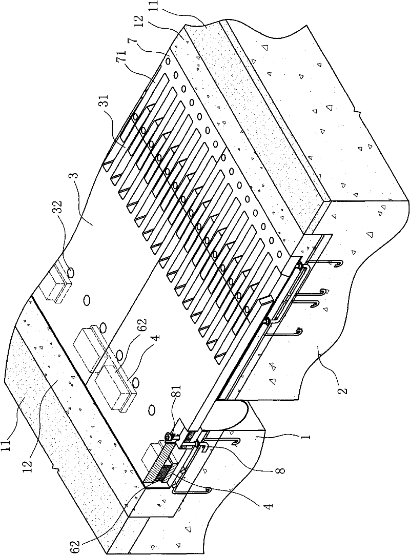
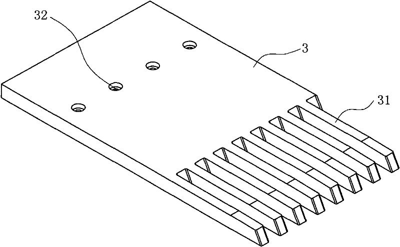
[0021] Such as Figure 1 ~ Figure 3 As shown, the noise-reducing bridge expansion joint device with vertical displacement function includes a first beam body 1 and a second beam body 2 located on both sides of the bridge expansion joint, and a movable comb arranged on the first beam body 1 Plate 3 and fixed comb plate 7 arranged on the second beam body 2;

[0022] Wherein, the movable comb plate 3 is a seam-spanning plate, the first end of the movable comb plate 3 is positioned on the first beam body 1 through the J-shaped fixing bolt 8, and the second end is positioned on the second beam body 2 and can be Move relative to the second beam body 2, the second end of the movable comb plate 3 is provided with comb teeth 31 and intersects with each comb tooth 71 of the fixed comb plate 7, and the end of each comb plate is connected to the corresponding beam body. A concrete layer 12 is poured between the road surfaces 11;

[0023] Between the bottom of the first end of the movabl...

Embodiment 2

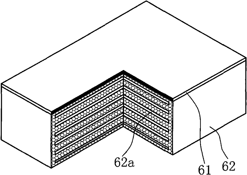
[0028] Such as Figure 4 ~ Figure 6 As shown, it is Embodiment 2 of the present invention, and what is different from Embodiment 1 is that a downwardly protruding positioning column 34 is provided at the bottom of the first end of the movable comb plate 3 (ie, the cross-slit plate), and the movable comb plate A hollow positioning box 5 fixed to the first beam body 1 is arranged under the first end of 3, and a positioning hole 51a is opened on the top plate 51 of the positioning box 5, and the end of the positioning column 34 passes through the positioning box 5. The positioning hole 51a extends into the positioning box 5 inside;

[0029] In this embodiment, a unit movable comb 3 is arranged with a group of plane slides 61, elastic liners 62 and support plates 4 and two sets of positioning columns 34, plane slides 61, elastic liners 62 and positioning boxes in its width direction. 5, see Figure 4 Shown in dotted line; Wherein, the thickness of support plate 4 is consistent w...


PUM


Abstract

The invention discloses a noise-reducing bridge expansion joint device with vertical displacement function, which comprises a seam-spanning plate (3) arranged on the bridge joint, and the first end of the seam-spanning plate (3) is passed through a fixing bolt ( 8) It is positioned on the first beam body (1) on one side of the bridge joint, and the second end is located on the second beam body (2) on the other side of the bridge joint and can move relative to the second beam body (2). Between the bottom of the first end of the slit plate (3) and the surface of the first beam body (1), a planar sliding plate (61) and an elastic lining plate (62) are sequentially arranged from top to bottom. Compared with the prior art, when the beam body is displaced vertically in the present invention, the first end of the seam-spanning plate can be adaptively displaced relative to the first beam body with the fixed bolt as the center line, which is simple and easy To ensure that the vehicle can pass through the bridge expansion joint surface smoothly; and to ensure that the span plate can always be in a stable and smooth moving state when it is displaced relative to the first beam body, basically without noise. Very environmentally friendly.

Description

technical field [0001] The invention relates to the technical field of bridge expansion joints, in particular to a noise-reducing bridge expansion joint device with a vertical displacement function. Background technique [0002] In the existing bridge expansion joint devices, no matter it is a comb-type plate type or a welded type, a spanning plate is arranged on the bridge expansion joint, and one end of the spanning plate is fixed on the beam body on one side of the bridge joint, and the other One end is located on the beam body on the other side of the bridge expansion joint and can move relative to the beam body. Such as the Chinese invention patent "A kind of extra-large deflection-resistant comb type bridge expansion joint device" that the patent No. ZL200410049491.5 (notification number is CN1333137C) that I proposed earlier is just like this. The fixed comb plate and the movable comb plate on the beam body on both sides of the seam, wherein, the first end of the mov...

Claims


Application Information

Patent Timeline
Patent Type & Authority Patents(China)
IPC IPC(8): E01D19/06
Inventor 徐斌
Owner NINGBO ROABY TECH INDAL GROUP
Why Eureka
Try Eureka