Matched prefabricated concrete hollow slab beam structure

A prefabricated concrete and hollow slab beam technology, applied in structural elements, truss structures, bridges, etc., can solve problems such as failure to prevent and control longitudinal cracks in the bottom plate, and achieve the effect of enhancing the overall effect, avoiding longitudinal cracks, and preventing rainwater immersion.

A prefabricated concrete and hollow slab beam technology, applied in structural elements, truss structures, bridges, etc., can solve problems such as failure to prevent and control longitudinal cracks in the bottom plate, and achieve the effect of enhancing the overall effect, avoiding longitudinal cracks, and preventing rainwater immersion.

CN101769042AInactive Publication Date: 2010-07-07HOHAI UNIV

Image

  • Matched prefabricated concrete hollow slab beam structure
  • Matched prefabricated concrete hollow slab beam structure

Examples


Embodiment Construction

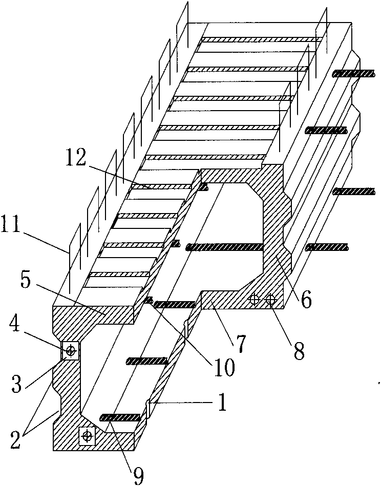
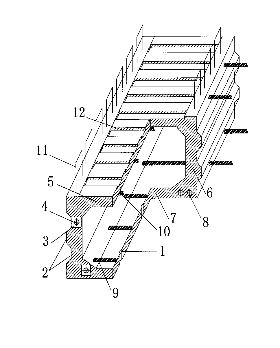
[0025] The accompanying drawings disclose non-restrictive structural schematic diagrams of specific embodiments involved in the present invention, and the technical solutions of the present invention will be described in detail below in conjunction with the accompanying drawings.

[0026] The matching prefabricated concrete hollow slab girder structure of the present invention includes a top plate 5, a web 6 and a bottom plate 7 surrounding a plate girder structure, a hollow cavity is arranged in the plate girder structure, and the top plate 5, web 6 and bottom plate 7 is formed by pouring concrete, and the outer surface of the web 6 is arranged with a shear key 2 in a prefabricated manner. Therefore, the present invention adopts the shear key 2 instead of the traditional hinge joint design, that is, in the prestressed concrete hollow slab described in the present invention During the beam prefabrication process, the cast hollow slab girder structure is used as the side form of...


PUM

PropertyMeasurementUnit
Diameteraaaaaaaaaa

Abstract

The invention discloses a matched prefabricated concrete hollow slab beam structure, which comprises a top slab, webs and a bottom slab which form the slab beam structure in an enclosing way. A hollow chamber is arranged in the slab beam structure. The top slab, the webs and the bottom slabs are poured by concrete. Shear keys are distributed on the surface of the webs in a matched prefabricating way. Thereby, the shear keys are used to substitute for hinge joints, the defect that concrete is difficult to be vibrated tightly when reinforcement is conducted in the narrow space of the hinge joints is avoided, the contradiction that the rigidity of the hinge joints is lower than the rigidity of the prestressed concrete hollow slab beam in the traditional hinge joint design is overcome, the prestress on the constructional longitudinal bridge and the constructional transverse bridge of the hollow slab beam, the cracks on the bottom slab and the damages of the hinge joints are prevented and controlled, and the current problem that the longitudinal cracks of the bottom slab cannot be prevented and controlled is solved.

Description

technical field [0001] The invention relates to a matching prefabricated concrete hollow slab beam structure, which belongs to the field of civil engineering bridge superstructure. Background technique [0002] At present, there are mainly three types of damage in the upper structure of prestressed concrete hollow slab girder bridges: transverse cracks in the bottom slab, longitudinal cracks in the bottom slab, and hinge joints. For cracks and hinged joints, the deep damage mechanism is still unclear, and there has been no substantial breakthrough in prevention and control measures. [0003] The longitudinal cracks of the bottom plate generally appear along the direction of the prestressed tendons or ordinary stressed steel bars, and once they appear, most of their lengths are greater than 1 / 3l, where l is the span of the beam. The current research shows that the longitudinal cracks in the bottom plate mainly have the following causes: premature tensioning of prestressed te...

Claims


Application Information

Patent Timeline
07 Jul 2010
Publication
CN101769042A
IPC
E04C3/26; E04C5/08; E01D2/00; E01D2/04; E01D101/28
Inventors
袁爱民; 朱晓文