
Solar collector installed with horizontally inserted, densely arranged and jacking evacuated solar collector tubes with location tube joints

A vacuum heat collection tube, installation and positioning technology, which is applied in the field of vacuum heat collection tube solar collectors, can solve the problems of high price, high production cost, and reduced service life of the whole machine, and achieve the effect of reasonable price, firm fixation, and good stability

Inactive Publication Date: 2013-07-10
ZIBO ENVIRONMENTAL PROTECTION TECH CO LTD +1
View PDF0 Cites 0 Cited by
  • Summary
  • Abstract
  • Description
  • Claims
  • Application Information

AI Technical Summary

Problems solved by technology

The latter type of heat pipe collector uses a vacuumed copper tube with a heat transfer medium that vaporizes at high temperature and condenses at low temperature. Due to the short life of the heat pipe, the life of the whole machine is also reduced, and the production cost is high and the price is high.
Moreover, these two split pressure-bearing vacuum heat collecting tube solar collectors only have the function of heat collection, and do not have the function of heat preservation, let alone the function of building materials.

Method used


Image

  • Solar collector installed with horizontally inserted, densely arranged and jacking evacuated solar collector tubes with location tube joints
  • Solar collector installed with horizontally inserted, densely arranged and jacking evacuated solar collector tubes with location tube joints
  • Solar collector installed with horizontally inserted, densely arranged and jacking evacuated solar collector tubes with location tube joints

Examples


Embodiment Construction

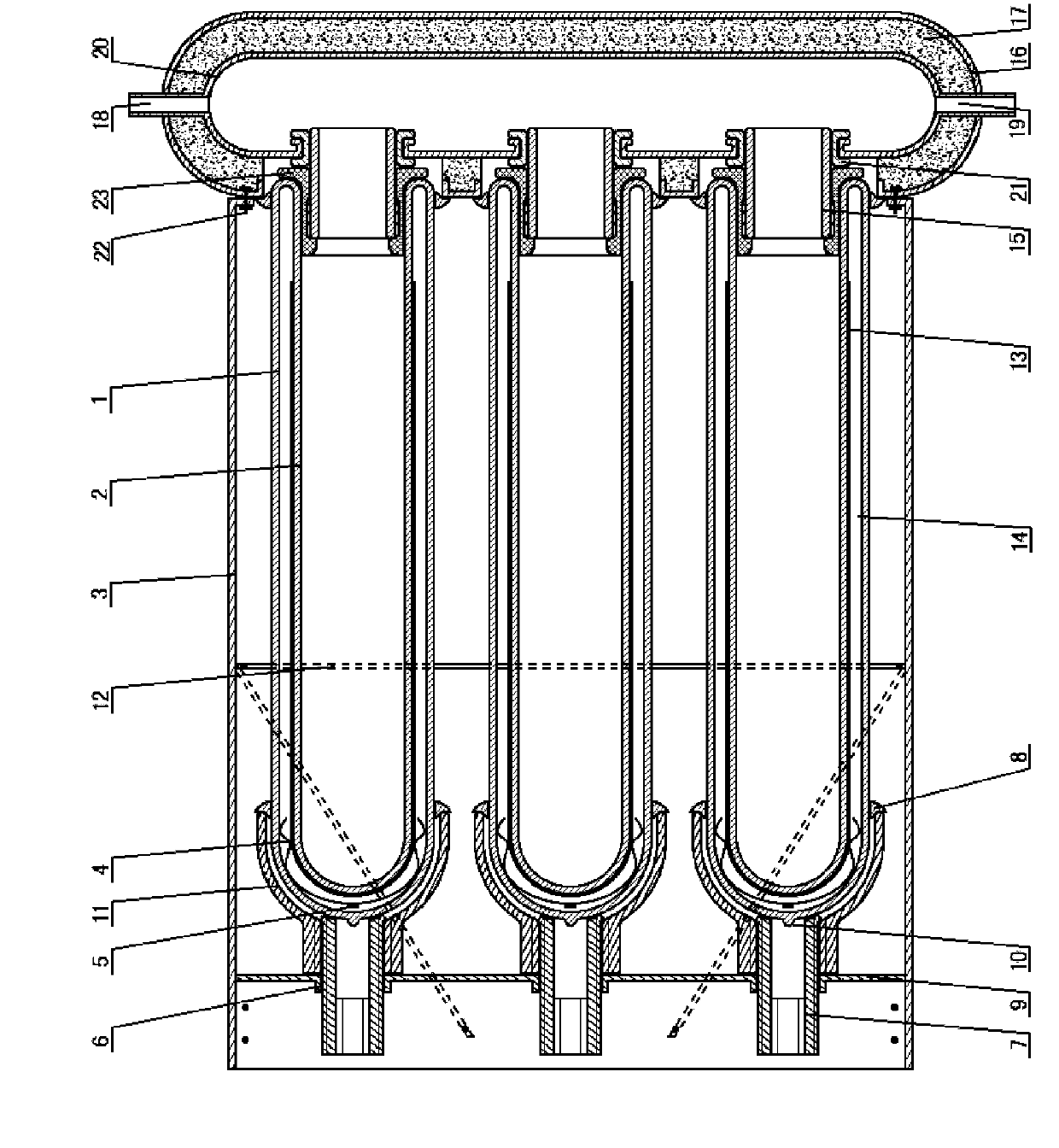
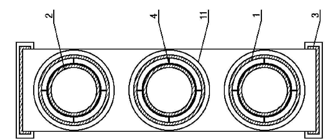
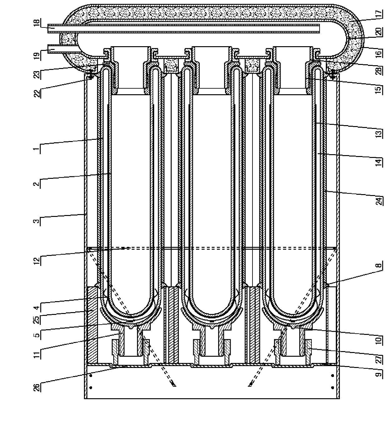
[0034] Such as figure 1 , figure 2 Shown: a solar collector with vacuum heat collecting tubes inserted horizontally and densely arranged on the top and tightly installed with positioning tube heads, including a water tank outer barrel 16, a water tank insulation layer 17, a water tank liner 19, a vacuum heat collecting tube, a fixed bracket 3, and a vacuum collector The heat pipe tailstock, the water tank liner 19 is placed in the water tank outer barrel 16, the water tank insulation layer 17 is established between the water tank liner 19 and the water tank outer barrel 16, and the water tank liner 19 is provided with a water inlet 18 and a water outlet 20. The water tank is vertically installed on one end of the fixed support 3, and the same side of the water tank outer barrel 16, the water tank insulation layer 17, and the water tank liner 19 have coaxial holes for inserting vacuum heat collecting tubes, and the vacuum heat collecting tubes are inserted into the mouth of th...


PUM


Abstract

The invention discloses a solar collector with horizontally inserted, densely arranged and jacking evacuated solar collector tubes with location tube joints, which comprises a water tank, evacuated solar collector tubes, a fixed support and tailstocks of the evacuated solar collector tubes, wherein a water inlet and a water outlet are arranged on the liner of the water tank. The water tank is longitudinally installed and fixed at one end of the support, coaxial holes for inserting the evacuated solar collector tubes are arranged at the same sides of the outer barrel, an insulating layer and the liner of the water tank, or the water tank is longitudinally installed and fixed in the middle of the support, and coaxial holes for inserting the evacuated solar collector tubes are arranged at the two sides of the outer barrel, the insulating layer and the liner of the water tank; and the location tube joints are inserted into the sealing rings of the pores of the liner, the tail ends of the evacuated solar collector tubes are tightly jacked by jacking tailstocks on the tailstock box of the bearing fixed support, and thereby the horizontally inserted and densely arranged installation of the evacuated solar collector tubes the tube orifices of which are inserted with the location tube joints is realized. The invention improves the stability and durability of a solar water heater system, realizes the perfect combination with buildings, and adds functions of heat insulation and building materials to the solar collector under the premise of maintaining the heat collecting function thereof.

Description

technical field [0001] The invention relates to a solar heat collector with vacuum heat collecting tubes inserted horizontally and densely arranged on the top and tightly installed with positioning pipe heads, which is suitable for solar water heating systems with high requirements for stability performance and high requirements for building combination. Background technique [0002] There are also some split pressure-bearing vacuum tube solar collectors on the market now, which are mainly divided into two types: 1. U-shaped tube collectors. 2. Heat pipe collector. The former U-shaped tube collector is also a medium in the metal tube through forced circulation heat exchange, the amount of copper tube is more, the welding requirements are higher, and the cost is also high. The latter type of heat pipe collector uses a vacuumized copper tube, which contains a heat transfer medium that vaporizes at high temperature and condenses at low temperature. Due to the short life of the...

Claims


Application Information

Patent Timeline
Patent Type & Authority Patents(China)
IPC IPC(8): F24J2/05F24J2/24F24J2/46F24S10/40F24S10/70
CPCY02E10/44
Inventor 徐宝安
Owner ZIBO ENVIRONMENTAL PROTECTION TECH CO LTD
Learn More