Method for testing control board of electromagnetic valve

A test method and solenoid valve technology, applied in the testing of machine/structural components, measuring devices, instruments, etc., can solve the problems of complex operation, inaccuracy, easy damage to switches, etc., and achieve high efficiency, high accuracy, and test methods. Simple and reliable effects

Active Publication Date: 2010-07-07
上海文安电脑技术有限公司
View PDF0 Cites 2 Cited by
  • Summary
  • Abstract
  • Description
  • Claims
  • Application Information

AI Technical Summary

Problems solved by technology

This detection method is complicated and imprecise, and the switch is easily damaged

Method used


Image

  • Method for testing control board of electromagnetic valve
  • Method for testing control board of electromagnetic valve
  • Method for testing control board of electromagnetic valve

Examples


Embodiment

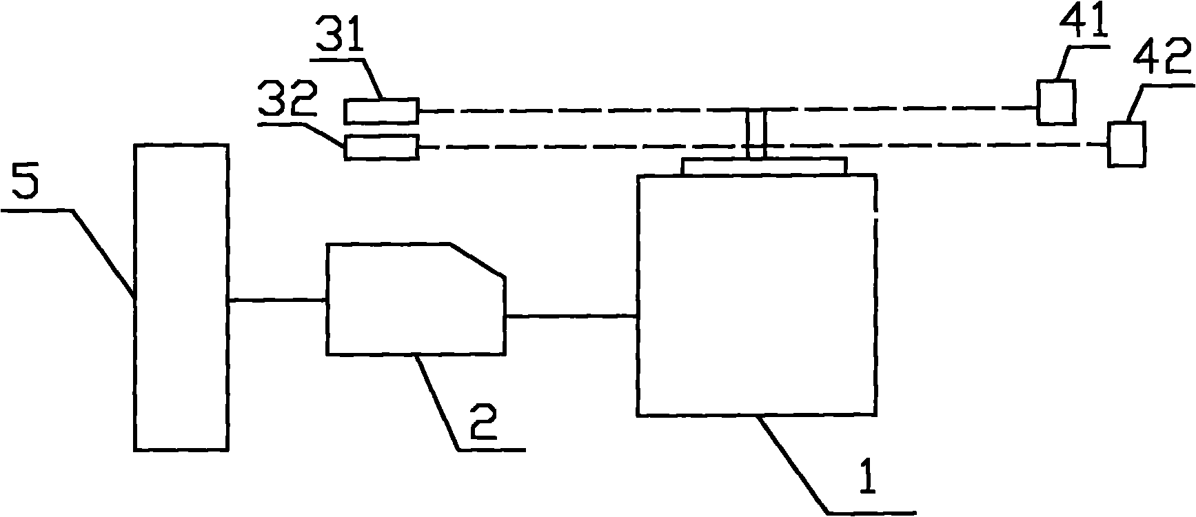
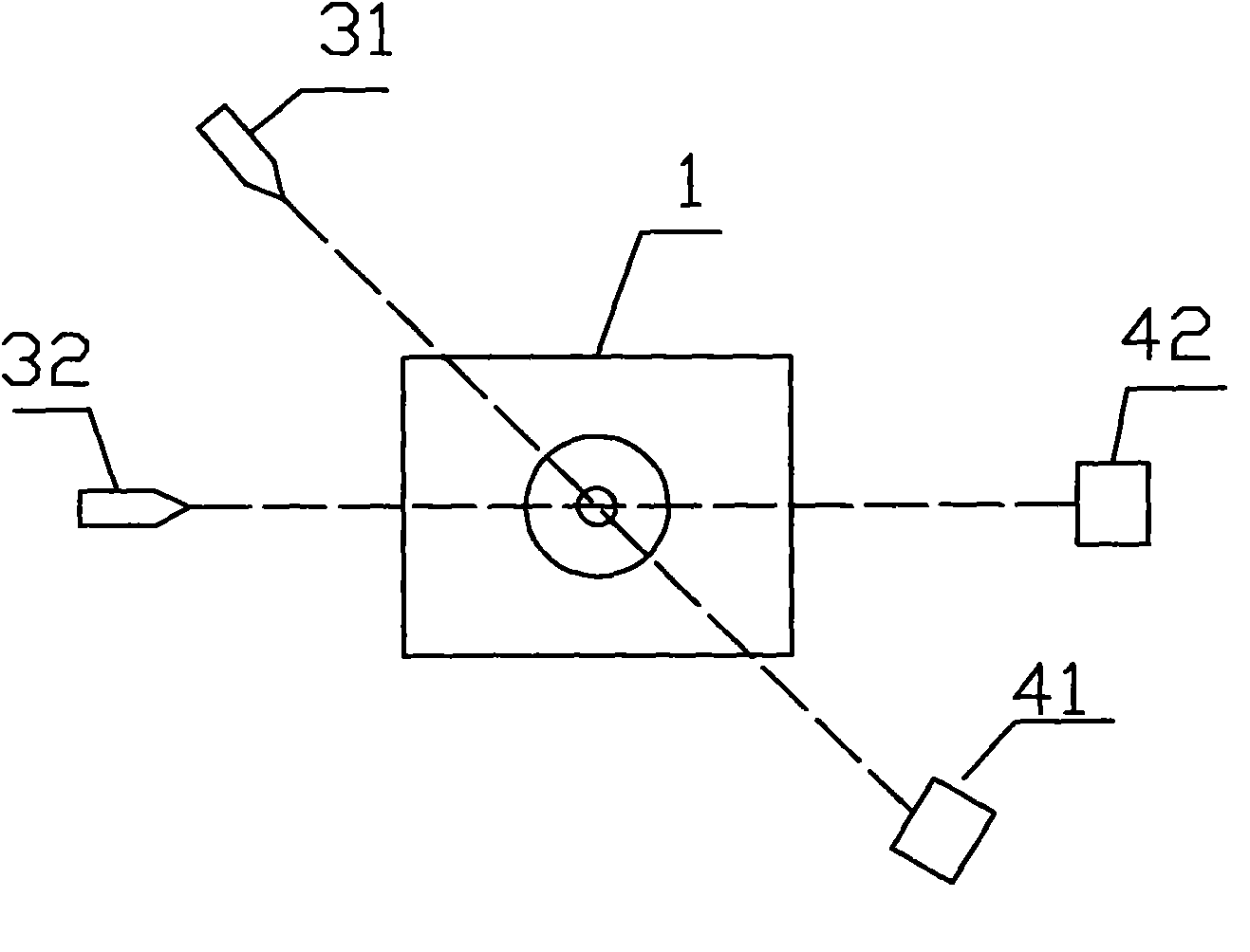
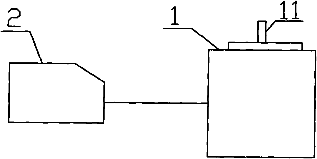
[0031] see figure 1 and figure 2 , implement the included device of the present invention to have: solenoid valve 1, solenoid valve control board 2, solenoid valve control board tester 5, laser emitter 31 and the photoelectric sensor 41 corresponding to the position, the photoelectric sensor corresponding to the laser emitter 32 and position 42, the photoelectric sensor 41 and the photoelectric sensor 42 can feed back the signal to the solenoid valve control board tester 5 after receiving the signal.

[0032] The method and steps of solenoid valve control board test of the present invention are as follows:

[0033] (1) First, two laser emitters 31, 32 and two photoelectric sensors 41, 42 are fixedly placed at different heights on both sides of the solenoid valve 1, and the laser emitter 31 and the photoelectric sensor 41 are correspondingly separated from the solenoid valve 1. The two sides of the solenoid valve 1 are at the same height; the laser emitter 32 is at the same ...


PUM


Abstract

The invention discloses a method for testing a control board of an electromagnetic valve, comprising the following steps of: (1) selecting an electromagnetic valve, respectively mounting laser emitters with different heights at two sides of the electromagnetic valve, and correspondingly mounting a photoelectric sensor at the other side of the electromagnetic valve provided with the laser emitter; (2) mounting the control board of the electromagnetic valve to be tested at the side of the electromagnetic valve, carrying out a test of starting delay time and releasing delay time on the control board of the electromagnetic valve through a magnetic valve control board tester, and sealing the tested control board of the electromagnetic valve with glue; (3) repeating the test of starting delay time and releasing delay time to the tested control board of the electromagnetic valve after the glue sealing, wherein the control board of the electromagnetic valve passing the secondary test is qualified. The test method of the invention is simple and reliable, the qualified control board of the electromagnetic valve has strong practicability and long service life.

Description

technical field [0001] The invention relates to a testing method for a solenoid valve control board applied to electromechanical equipment. Background technique [0002] Solenoid valve is an automatic basic component used to control the direction of fluid. It belongs to actuator. It is usually used on mechanical control and industrial valves to control the direction of medium, so as to control the valve switch. [0003] There is a closed cavity in the solenoid valve, and there are through holes in different positions. Each hole leads to a different oil pipe. There is a valve in the middle of the cavity, and two electromagnets on both sides. Wherever you go, you can block or expose different oil discharge holes by controlling the movement of the valve body, and the oil inlet hole is normally open, and the hydraulic oil will enter different oil discharge pipes. Then the piston of the oil cylinder is pushed by the pressure of the oil, the piston drives the piston rod, and the ...

Claims


Application Information

Patent Timeline
Patent Type & Authority Applications(China)
IPC IPC(8): G01M19/00G01M99/00
Inventor 白三山吴齐霖
Owner 上海文安电脑技术有限公司
Why Eureka
Try Eureka