Tab cutting device

A cutting and tab technology, used in shearing devices, shearing machines, metal processing equipment, etc., can solve the problems of inability to rectify and adjust, the cutting tool is fixed, and the quality of the tabs is affected, so as to improve the cutting quality, Effective and uniform cutting force, avoiding edge burrs

Active Publication Date: 2010-07-14
SHENZHEN YINGHE TECH
View PDF1 Cites 36 Cited by
  • Summary
  • Abstract
  • Description
  • Claims
  • Application Information

AI Technical Summary

Problems solved by technology

However, since the pneumatic cutter is driven by the cylinder and relies on the instantaneous impact force of the straight line to cut, it is easy to cause edge burrs on the cut tabs and affect the quality of the tabs; in addition, in this driving mode, the pneumatic cutter and the The fixed knife can ...

Method used


Image

  • Tab cutting device
  • Tab cutting device
  • Tab cutting device

Examples


Embodiment Construction

[0022] The present invention will be further described in detail below through embodiments in conjunction with the accompanying drawings.

[0023] In one embodiment, the tab cutting device includes a driving mechanism and a cutting mechanism.

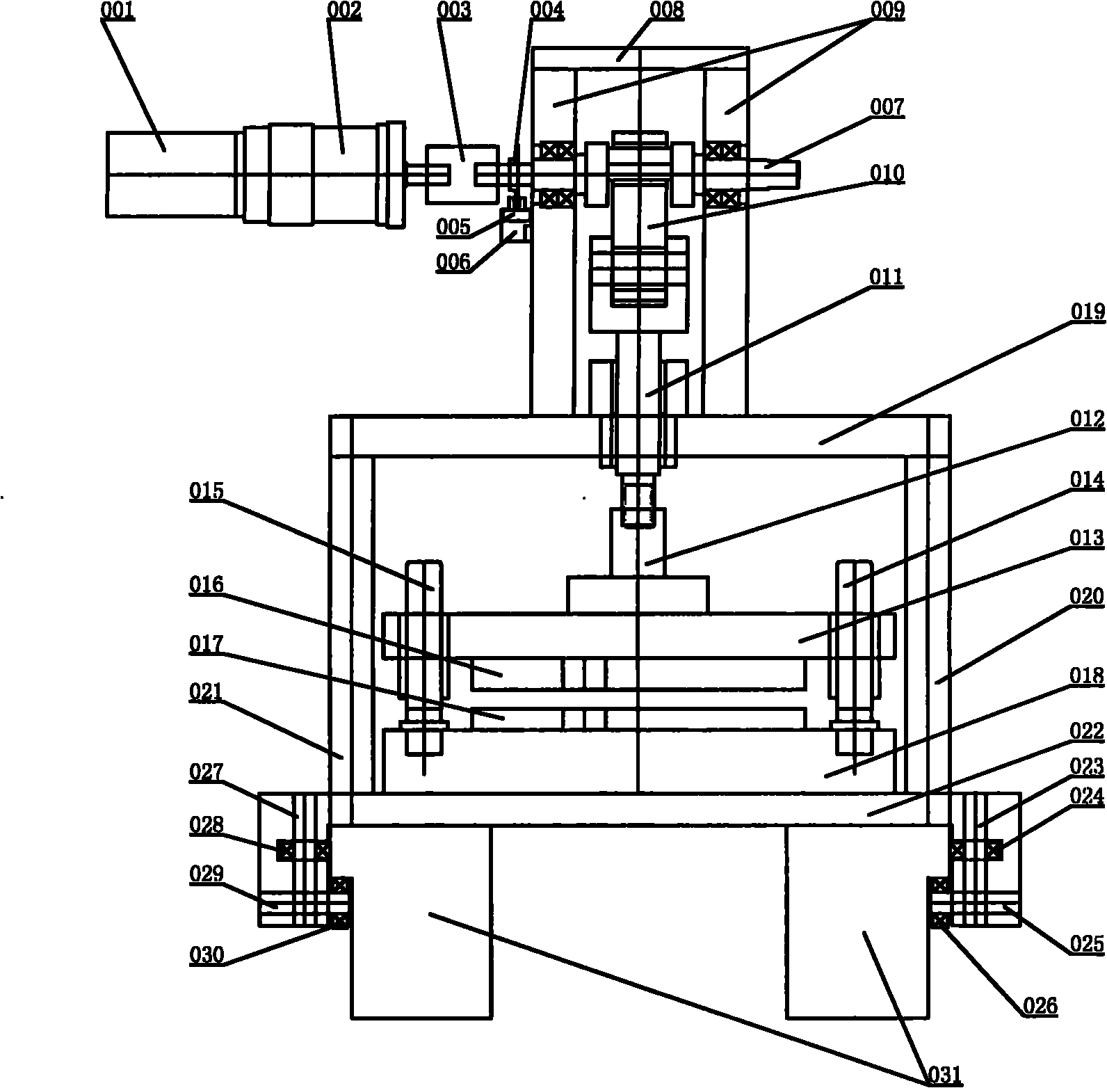
[0024] Please refer to figure 1 , the driving mechanism includes a motor 001, a reducer 002, a shaft coupling 003, an optical code disc 004, an inductor 005, an inductor bracket 006, a rotating shaft 007, a fixed block 008, a connecting block 009, a cam 010, and a first connecting rod 011.

[0025] Wherein, the output shaft of the motor 001 is fixedly connected with the rotating shaft 007 through the reducer 002 and the coupling 003, so that the rotating shaft 007 is driven by the motor 001 to rotate synchronously. The optical code disc 004, the sensor 005, and the sensor bracket 006 constitute an origin detection device. The optical code disc 004 is fixedly installed on the rotating shaft 007, and a gap is provided on the optical cod...


PUM


Abstract

The invention discloses a tab cutting device, which comprises a driving mechanism and a cutting mechanism, wherein the cutting mechanism comprises an upper cutter and a lower cutter; the driving mechanism is coupled with the upper cutter and comprises a motor, a cam and an in-situ detection device; the output shaft of the motor is coupled with the upper cutter by the cam; the motor drives the cam to rotate synchronously; the cam rotates to drive the upper cutter to move relative to the lower cutter to cut a tab. The device can ensure that the upper cutter can achieve an excellent tab cutting effect.

Description

technical field [0001] The invention relates to a tab cutting device, in particular to a tab cutting device used on pole pieces for large-scale lithium battery stacks. Background technique [0002] With the widespread application of lithium battery lamination equipment, the requirements for the pole pieces required by lithium battery lamination equipment are also getting higher and higher. Traditional tab cutting equipment, such as Chinese patent application No. 200710067425.4, discloses a cutting tool for lithium-ion battery tabs. The automatic tab cutting machine is provided with a pneumatic cutter, a fixed knife and a cylinder, and a fixed knife and a cylinder Installed on the workbench, the pneumatic cutter is installed on the cylinder, and the cylinder is connected with the cutter control switch. When the cylinder is activated, the pneumatic cutter moves toward the fixed knife under the drive of the cylinder to cut the tab. However, since the pneumatic cutter is driven...

Claims


Application Information

Patent Timeline
IPC IPC(8): B23D15/12B23D15/04
Inventor 王胜玲崔锁劳
Owner SHENZHEN YINGHE TECH
Why Eureka
Try Eureka