
Pneumatic gasbag-type semi-automatic polyurethane foaming and molding device

A foam molding and semi-automatic technology, which is applied in the field of pneumatic airbag-type semi-automatic polyurethane foam molding devices, can solve the problems of low yield, large waste and low production efficiency.

Active Publication Date: 2010-07-14
NINGBO FANGZHENG TOOL
View PDF0 Cites 7 Cited by
  • Summary
  • Abstract
  • Description
  • Claims
  • Application Information

AI Technical Summary

Problems solved by technology

Existing manual devices are labor-intensive in actual mass production, and the delayed curing time is controlled manually by watching the clock. The foaming density of the product is uneven, and it is difficult to control defects such as air bubbles and material shortages, resulting in low yield and large waste. Problems and deficiencies such as low efficiency, high cost of labor and material consumption, and poor consistency of product quality

Method used


Image

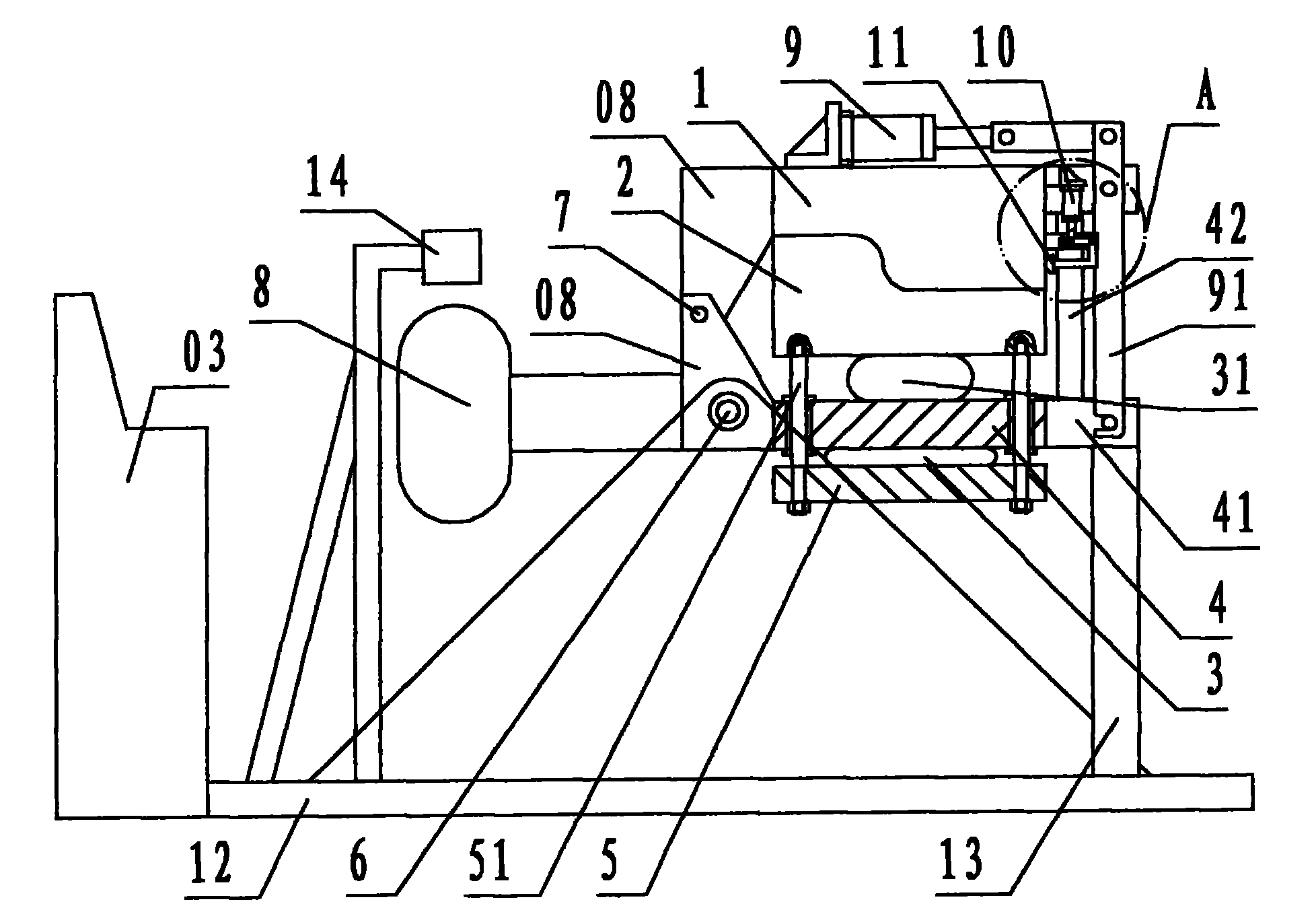
  • Pneumatic gasbag-type semi-automatic polyurethane foaming and molding device
  • Pneumatic gasbag-type semi-automatic polyurethane foaming and molding device
  • Pneumatic gasbag-type semi-automatic polyurethane foaming and molding device

Examples


Embodiment 1

[0029] Embodiment 1: basic structural form

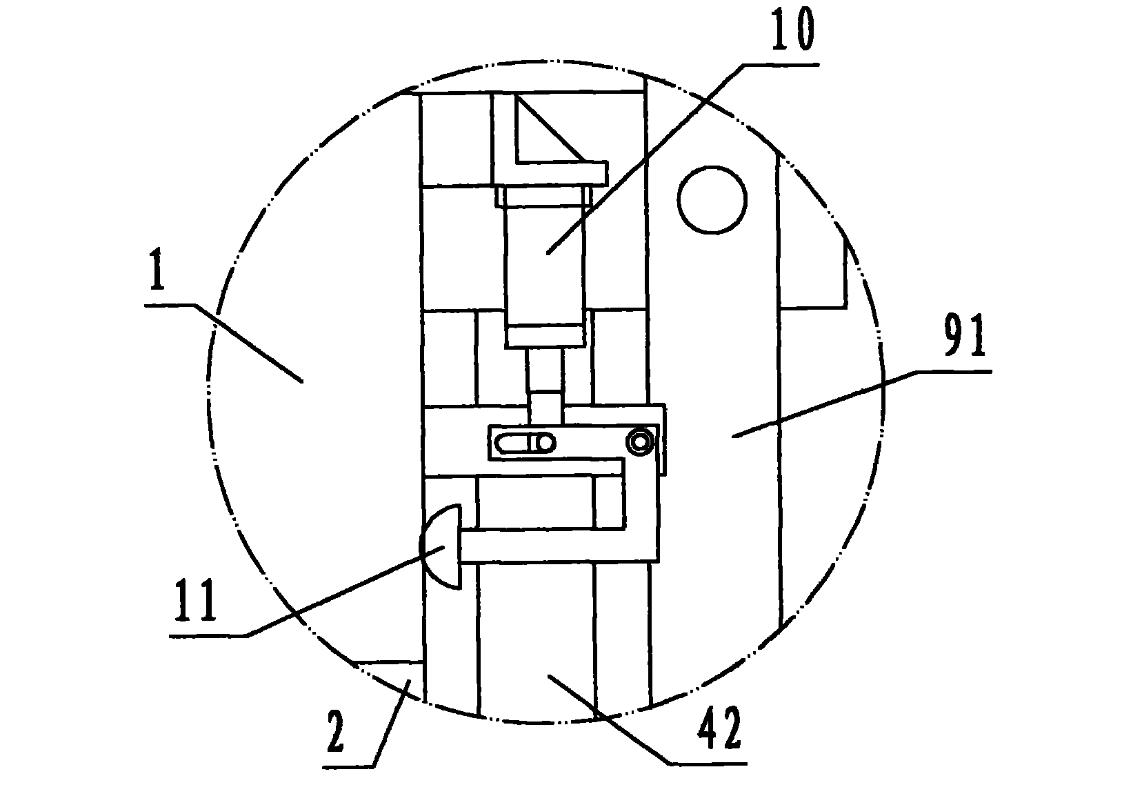
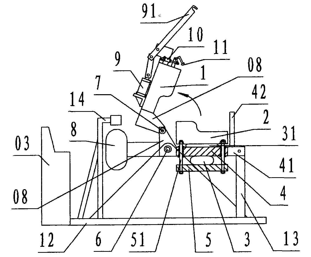
[0030] refer to Figure 1 to Figure 10, a pneumatic airbag type semi-automatic polyurethane foam molding device of the present invention, comprising a mold part, a pneumatic mold clamping part, a pneumatic sealing part, a rotating support part, and an electrical control part, wherein: the mold part is composed of the above Mold 1 and movable mold 2 are composed of upper mold 1 at the top and movable mold 2 at the bottom. Upper mold 1 and movable mold 2 are respectively equipped with half-valve cavities for the product, and cooperate with each other up and down through the corresponding parting surface; The inner cavity wall of the mold 1 is provided with a vent hole leading directly to the outer wall of the upper mold, and the front and rear sides of the left side of the upper mold 1 are provided with an extended pivot plate 08 with a shaft hole, and the pivot plate 08 of the upper mold 1 The opening and closing pivot 7 of the pneu...

Embodiment 2

[0039] Embodiment 2: Pneumatic airbag type semi-automatic polyurethane foam molding device for automobile seat backrest

[0040] refer to Figure 11 , Figure 12 , as shown in the figure, on the basis of the basic structure of Example 1, according to the specific car seat pillow products and operating requirements, additional mold feet 01, self-locking handle 02, button switch 04, rotating core 05, core Rocker 06, core lock pin 07 and other mechanism devices;

[0041] Before clamping the mold, manually rotate the core handle 06 to rotate the rotating core 05 and insert it into the cavity of the upper mold 1, and the core locking pin 07 automatically locks the rotating core 05 by spring and pawl;

[0042] When taking out product 09, mention core lock pin 07, manual core rocker 06, rotate core 05 together with product 09 and turn out the cavity of upper mold 1, product 09 is extracted from rotating core 05 manually.


PUM


Abstract

The invention discloses a pneumatic gasbag-type semi-automatic polyurethane foaming and molding device, which consists of a mold part, a pneumatic mold-closing and mold-locking part, a pneumatic sealing part, a rotary supporting part and an electrical control part. By adopting the technical scheme that a pneumatic air cylinder is controlled to automatically lock a mold and open or seal the air vent of the mold through a time sequence and the mold is opened and closed by using an upper gasbag and a lower gasbag, the problems of the conventional manual devices such as low rate of finished products, serious waste, low production efficiency, high labor cost and material cost, and poor consistency of the quality of products are solved. The provided pneumatic gasbag-type semi-automatic polyurethane foaming and molding device makes pneumatic foaming and molding production fulfill the aims of reducing labor intensity, improving the rate of finished products, reducing waste, improving production efficiency, decreasing labor cost and material cost and improving the consistency of the quality of the products through a time-controlled pneumatic semi-automatic operation mode.

Description

technical field [0001] The present invention relates to a foam molding device, specifically refers to a device for two-component polyurethane foam molding products, which utilizes an air bag to open and close the mold, and uses a time-controlled pneumatic cylinder to automatically lock the mold, open or block the exhaust port of the mold. Pneumatic air bag semi-automatic polyurethane foam molding device. Background technique [0002] The two-component polyurethane foam molding device of the prior art is a hand-molded mold device connected and opened by hinges, from mold opening, pouring, mold closing, mold locking, rotating mold, air blocking port, delayed curing , to open the mold and take out the whole production process of the product, all completed by manual operation. Existing manual devices are labor-intensive in actual mass production, and the delayed curing time is controlled manually by watching the clock. The foaming density of the product is uneven, and it is dif...

Claims


Application Information

Patent Timeline
IPC IPC(8): B29C44/34B29C44/58B29C44/60
Inventor 方永杰
Owner NINGBO FANGZHENG TOOL
Learn More