
Tower type combined drive pumping unit without guide wheel

一种组合传动、抽油机的技术,应用在传动装置、机械设备、皮带/链条/齿轮等方向,能够解决影响制约大规模的推广与应用、抽油杆和井口损坏、不能同时处理好等问题,达到设备紧凑、减少动力损失、重心平稳的效果

Active Publication Date: 2010-07-14
SICHUAN MODERN CENTURY MECHANICAL & ELECTRICAL COMPANY
View PDF0 Cites 21 Cited by
  • Summary
  • Abstract
  • Description
  • Claims
  • Application Information

AI Technical Summary

Problems solved by technology

[0002] At present, in the field of oil exploitation, the tower pumping unit is gradually replacing the beam pumping unit due to its simple structure, low cost, and low energy consumption. However, at the same time, the tower pumping unit itself has several interrelated The technical problems are also affecting and restricting its large-scale promotion and application. Among these technical problems, the two most prominent ones are workover way and wire rope life.
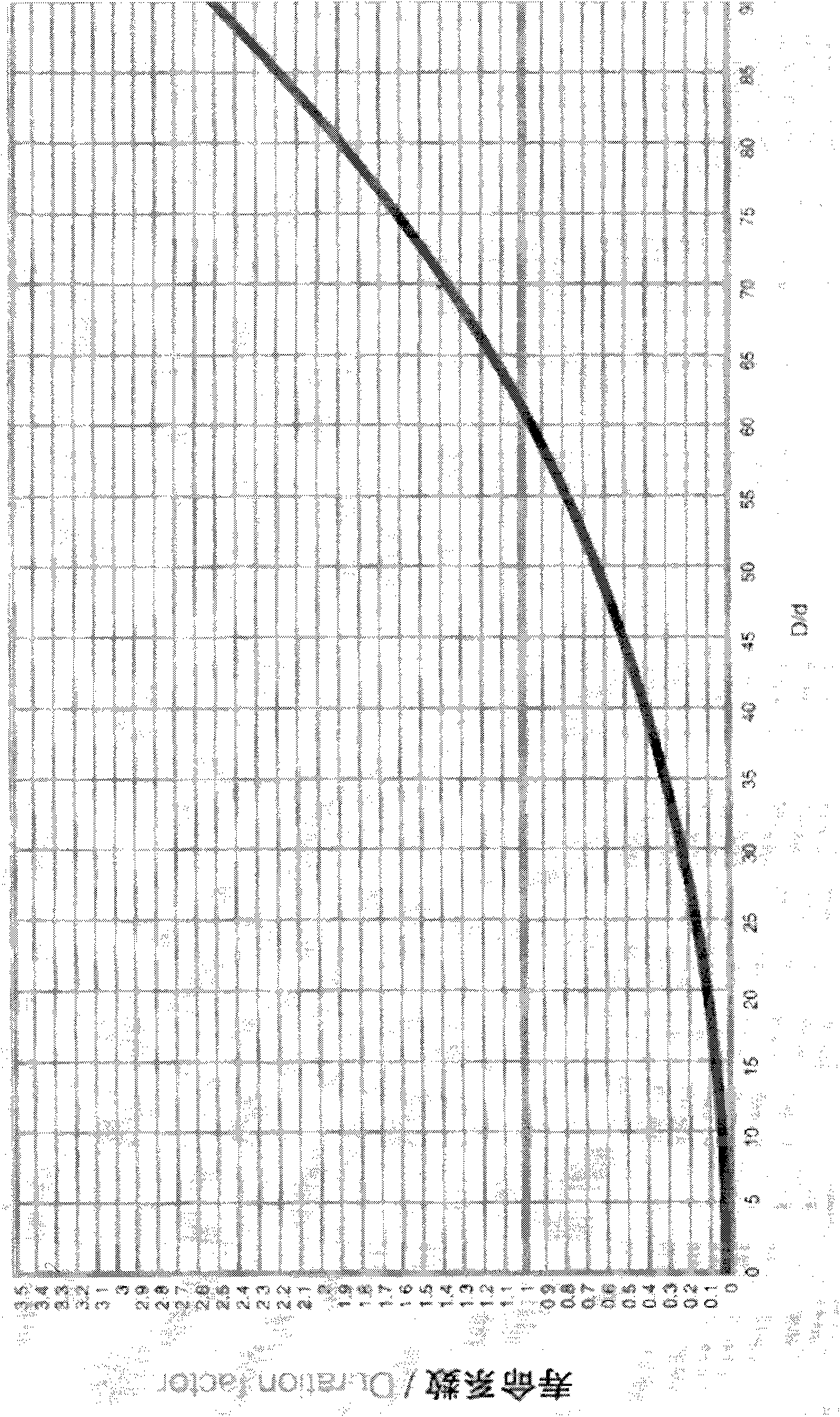
Before the workover work, in order to ensure that the workover equipment has enough space to operate at the wellhead, the minimum distance between the tower and the wellhead must be guaranteed to be more than 700mm. Therefore, there are two most common ways of workover at present. One is The entire tower is set to be movable. Before the workover, use the traction equipment to drag the entire tower away from the wellhead. Since the main equipment of the tower pumping unit is set on the top of the tower, the center of gravity is high, so the overall movement The tower is time-consuming and labor-intensive, and the safety is low; the second is to set the guide wheel protruding outward on the top of the tower. Since the distance of the guide wheel protruding outward can be adjusted as required, it can be guaranteed when the tower is installed. The distance from the wellhead is greater than 700mm, but considering factors such as tower stability and cost, the diameter of the guide wheel is generally small, and the service life of the steel wire rope is closely related to its bending diameter. Pulley and guide pulley, under the condition that the stress cannot be completely eliminated, the continuous inflection accelerates the damage of the wire rope, such as figure 1 In the diagram of the relative bending fatigue life coefficient of the steel wire rope, it is assumed that when the ratio of the bending diameter D of the steel wire rope to the diameter d of the steel wire rope is 62, the service life coefficient of the steel wire rope is 1, and the larger the ratio, the longer its service life , while the ratio of the diameter of the guide wheel used in the tower pumping unit with a load of less than 12 tons to the diameter of the wire rope is only about 40-50, and the guide wheel used in the tower pumping unit with a load of more than 12 tons The ratio of the diameter of the steel wire rope to the diameter of the wire rope is only about 25-35, so the service life of the wire rope is shortened due to the smaller diameter guide wheel
At present, there are still some tower pumping units that use belts instead of wire ropes to solve the problem of wire rope life, but the belts will swing violently under the force of the wind, which is easy to cause damage to the sucker rod and wellhead of the pumping unit
None of the existing tower pumping units can handle the above-mentioned technical problems at the same time

Method used

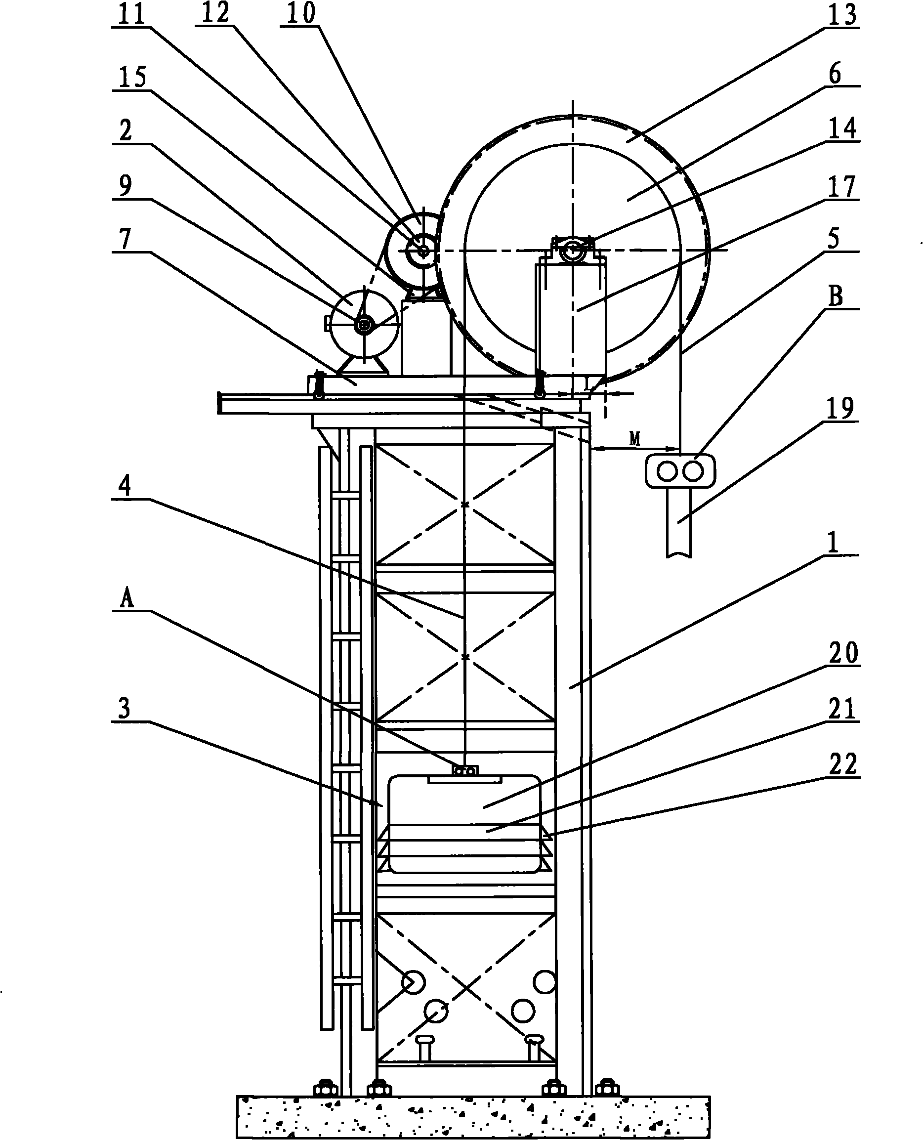
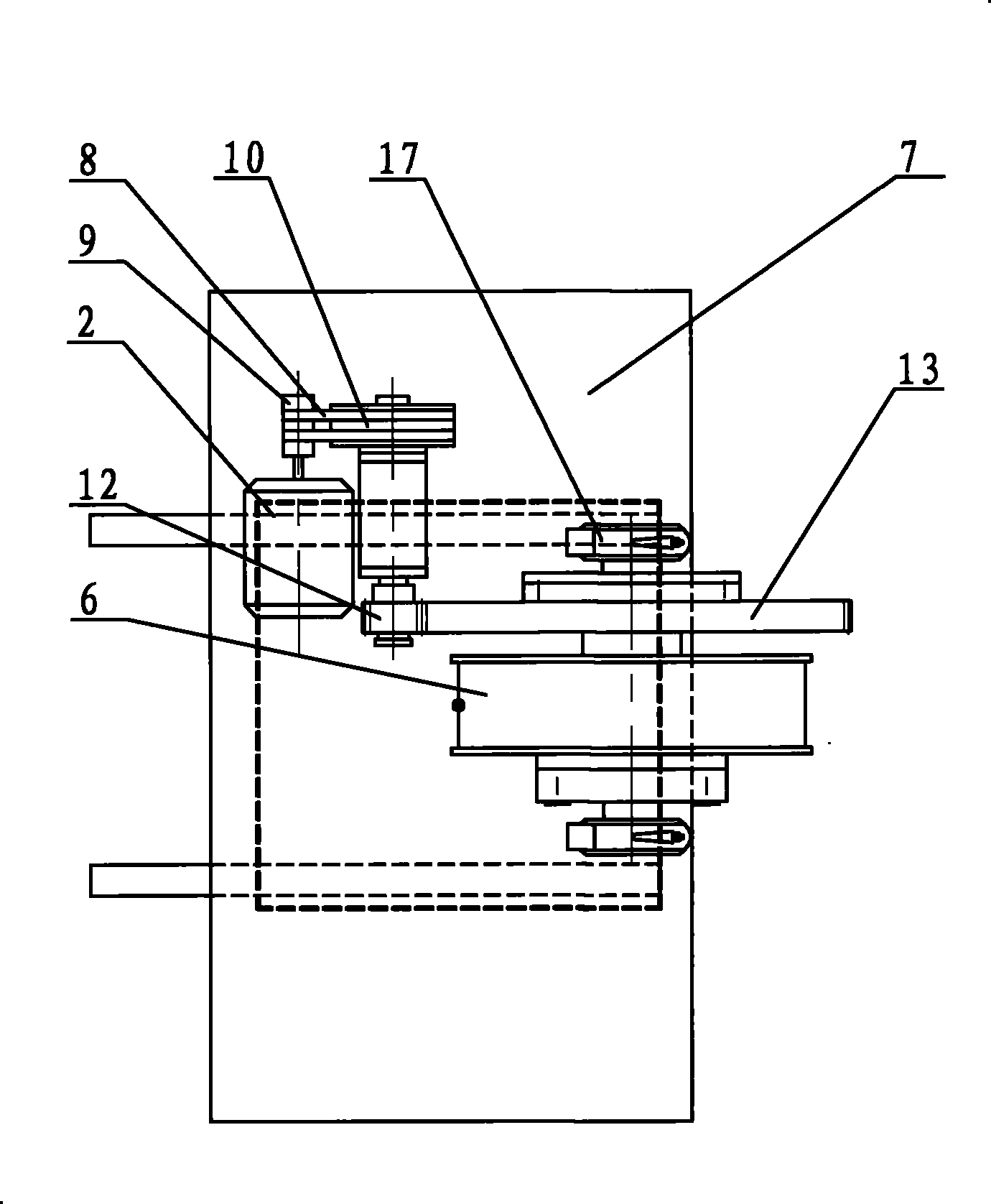

Image

  • Tower type combined drive pumping unit without guide wheel
  • Tower type combined drive pumping unit without guide wheel
  • Tower type combined drive pumping unit without guide wheel

Examples


Embodiment approach

[0023] like figure 2 and image 3 The shown tower type combined transmission pumping unit without guide wheels is the first embodiment of the present invention, including a tower 1, a power system 2, a transmission system, a control system, a balance counterweight box 3, a counterweight traction rope 4, Drive rope 5 and rope hanger, wherein power system 2, transmission system and sheave 6 are installed on the operating platform 7 on the top of tower 1, power system 2 is permanent magnet synchronous brake motor, and control system is installed on permanent magnet synchronous brake motor. In the motor, the staff can control and operate the entire tower-type guide wheel-less combined transmission pumping unit under the tower 1 through the wireless or wired controller of the control system. combine Figure 5As shown, the transmission system includes a transmission belt 8, a small belt sprocket 9, a large belt sprocket 10, a transmission shaft 11, a pinion 12, a large gear 13 an...


PUM


Abstract

The invention discloses a tower type combined drive pumping unit without a guide wheel, relates to petroleum exploitation equipment, and aims to provide the tower type pumping unit which can safely and conveniently repair a well and has long service life of a steel wire rope. The pumping unit comprises a tower, a power system, a transmission system, a control system, a balance weight box, a weighting hauling cable, a rope wheel, a drive rope and a beam hanger, wherein the rope wheel is fixed on one side of an operating platform through a rope wheel supporting device, a central axis of the rope wheel is positioned in the operating platform, and the shortest distance from the central axis to the edge of the operating platform in a horizontal direction is L; an edge of the rope wheel stretches out of the operating platform, and the shortest distance from the edge of an outermost end to the tower in the horizontal direction is M; the weighting hauling cable and the drive rope are wound on the rope wheel in the opposite direction, a free end of the weighting hauling cable is connected with the balance weight box through the beam hanger A, and a free end of the drive rope is connected with a pumping rod through the beam hanger B; and a platform moving device is arranged between the operating platform and the top of the tower, wherein L is not less than 50mm; and M in not less than 700mm.

Description

technical field [0001] The present invention relates to a kind of petroleum exploitation mechanical equipment, particularly relates to a kind of tower type pumping unit. Background technique [0002] At present, in the field of oil exploitation, the tower pumping unit is gradually replacing the beam pumping unit due to its simple structure, low cost, and low energy consumption. However, at the same time, the tower pumping unit itself has several interrelated The technical problems are also affecting and restricting its large-scale promotion and application. Among these technical problems, the two most prominent ones are the workover way and the life of the steel wire rope. Before the workover work, in order to ensure that the workover equipment has enough space to operate at the wellhead, the minimum distance between the tower and the wellhead must be guaranteed to be more than 700mm. Therefore, there are two most common ways of workover at present. One is The entire tower ...

Claims


Application Information

Patent Timeline
Patent Type & Authority Applications(China)
IPC IPC(8): E21B43/00F16H37/12
CPCE21B43/126E21B15/003
Inventor 毛宏伟
Owner SICHUAN MODERN CENTURY MECHANICAL & ELECTRICAL COMPANY
Learn More