Combustion-supporting device of furnace

A furnace and furnace body technology, which is applied in the direction of combustion method, combustion equipment, non-flammable liquid/gas transportation, etc., can solve the problems of waste of energy, short service life of the grate, blockage of the grate, etc., and achieve the effect of increasing combustion Effect

Inactive Publication Date: 2012-11-14
NINGBO ZHENHAI JIEDENG APPL TECH INST
View PDF1 Cites 0 Cited by
  • Summary
  • Abstract
  • Description
  • Claims
  • Application Information

AI Technical Summary

Problems solved by technology

[0002] Stoves are an indispensable tool in people's daily life. They are used for cooking, cooking, boiling water, and heat preservation. Efficiency and environmental protection have attracted more and more attention from human beings. People have been making unremitting efforts, and there are more and more types of stoves, but they still have not gotten rid of the problems of low efficiency, pollution, and waste of energy. Changes in fuel quality or improper operation will not only waste energy, but also cause environmental pollution. For example, the patent No. 200920174179.7 is a combustion-supporting device for a stove. However, since the device is a certain distance away from the grate, and the grate is easily blocked by the residual ash left by the combustion, the suction force of the air sucked into the combustion chamber from the air inlet is limited, so when the nozzle sprays high-temperature gas It can only stir the air in the combustion chamber, and it is difficult to achieve the best combustion state, and because the temperature in the combustion chamber is too high, the grate will be deformed, resulting in a short service life of the grate

Method used


Image

  • Combustion-supporting device of furnace

Examples


Embodiment Construction

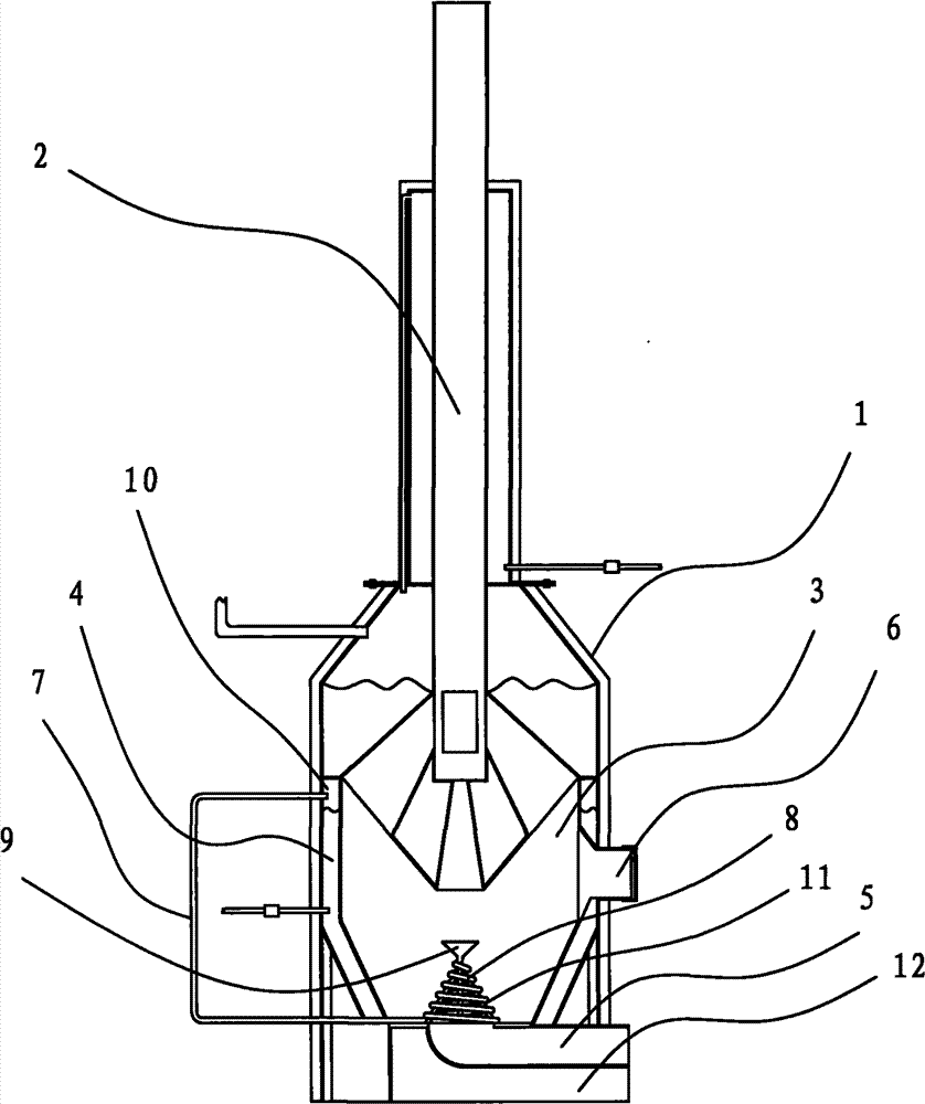
[0010] The present invention will be further described in detail below in conjunction with the accompanying drawings and embodiments.

[0011] As shown in the figure, a combustion-supporting device for a furnace includes a furnace body 1 and a chimney 2, the chimney 2 is arranged on the furnace body 1, a combustion chamber 3 is arranged in the furnace body 1, and a water storage layer 4 is arranged around the combustion chamber 3. A steam chamber 10 is arranged above the water storage layer 4, and the steam chamber 10 is connected with a steam pipe 7. A furnace door 6 is arranged on one side of the combustion chamber 3, and an air inlet 5 is arranged at the lower end of the combustion chamber 3, and the air inlet 5 is connected with the combustion chamber. 3 is provided with a grate 8 made of hollow tubes, the grate 8 is connected to the steam chamber 10 through the steam pipe 7, a spray head 9 is arranged above the grate 8, and a support for the grate 8 is arranged below the g...


PUM


Abstract

The invention discloses a combustion-supporting device of a furnace, which comprises a furnace body and a chimney, wherein the chimney is arranged on the furnace body; a combustion chamber is arranged in the furnace body; one side of the combustion chamber is provided with a furnace door; and the lower end of the combustion chamber is provided with an air intake. The combustion-supporting device is characterized in that a water storage layer is arranged around the combustion chamber; a steam chamber is arranged above the water storage layer; the steam chamber is connected with a steam pipe; afurnace bar made of hollow pipes is arranged between the air intake and the combustion chamber; the furnace bar is communicated with the steam chamber by the steam pipe; and an injector head is arranged above the furnace bar. The invention has the advantages that the furnace bar made of the hollow pipes is arranged between the air intake and the combustion chamber, and the injector head is arranged above the furnace bar, and therefore, steam can be sprayed into the combustion chamber to agitate air in the combustion chamber, thereby taking the combustion-supporting effect and greatly saving fuels.

Description

technical field [0001] The invention relates to a furnace, in particular to a combustion-supporting device for a furnace. Background technique [0002] Stoves are an indispensable tool in people's daily life. They are used for cooking, cooking, boiling water, and heat preservation. Efficiency and environmental protection have attracted more and more attention from human beings. People have been making unremitting efforts, and there are more and more types of stoves, but they still have not gotten rid of the problems of low efficiency, pollution, and waste of energy. Changes in fuel quality or improper operation will not only waste energy, but also cause environmental pollution. For example, the patent No. 200920174179.7 is a combustion-supporting device for a stove. However, since the device is a certain distance away from the grate, and the grate is easily blocked by the residual ash left by the combustion, the suction force of the air sucked into the combustion chamber fr...

Claims


Application Information

Patent Timeline
Patent Type & Authority Patents(China)
IPC IPC(8): F23L7/00
Inventor 陈兆红
Owner NINGBO ZHENHAI JIEDENG APPL TECH INST
Why Eureka
Try Eureka