
Light emitting diode (LED) magnetic adsorption and positioning aluminum wire bonding machine with cross guide rail transfer table

A cross guide rail and magnetic adsorption technology, which is applied to semiconductor devices, electrical components, circuits, etc., can solve the problems of inability to meet processing requirements, unstable welding quality, and low efficiency

Inactive Publication Date: 2012-01-04
陈炜旻
View PDF4 Cites 0 Cited by
  • Summary
  • Abstract
  • Description
  • Claims
  • Application Information

AI Technical Summary

Problems solved by technology

The former method has low work efficiency, and the welding quality is very unstable after wire bonding, while the latter method cannot be realized in the LED in-line electrode holder
For the "Light Emitting Diode" patent No. 200510022149.0 applied by Mr. Chen Ze to the Chinese Patent Office, patent publication number: CN100392880C "Light Emitting Diode" patent No. 200510021787.0 patent publication number: CN100373645C, the external lead electrode with insulating separation beads is a soft lead LED in-line electrode bracket, automated large-scale industrial production requires the use of a conjoined frame that connects the LED in-line electrode bracket. The LED in-line electrode bracket must be assembled and clamped before subsequent processing (generally one-time assembly) clamping capacity is 500 to 600 pieces), the first two methods cannot meet the processing requirements, so there are defects that need to be improved

Method used


Image

  • Light emitting diode (LED) magnetic adsorption and positioning aluminum wire bonding machine with cross guide rail transfer table
  • Light emitting diode (LED) magnetic adsorption and positioning aluminum wire bonding machine with cross guide rail transfer table
  • Light emitting diode (LED) magnetic adsorption and positioning aluminum wire bonding machine with cross guide rail transfer table

Examples


Embodiment Construction

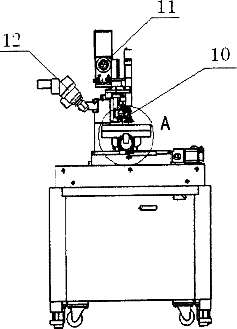
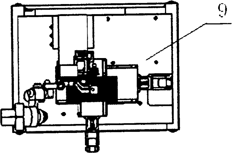
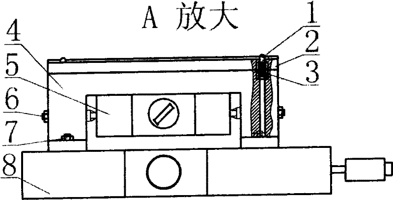
[0013] Firstly, place the cross rail shift table on the given position of the base plate of the LED cross rail shift table magnetic adsorption positioning aluminum wire punching machine, and use the cross rail shift table connecting screws to realize the fixed connection between the cross guide rail shift table and the machine base. Type positioning pin on the upper surface of the bridge-type support seat, and then place the magnet of the magnetic table base in the center of the bridge-type support seat, and make the upper surface of the magnetic table base flat with the bridge-type support seat, and fix the magnetic table base with the fixing screw. The table base is fixed with the bridge-shaped support seat, and then the bridge-shaped support seat with the magnetic table base fixed and the cross guide rail moving table are fixed with connecting screws. Then the pressure spring is put into the evenly distributed spring seat holes on the bridge-shaped bearing seat, and then the...


PUM


Abstract

The invention discloses a light emitting diode (LED) magnetic adsorption and positioning aluminum wire bonding machine with a cross guide rail transfer table, which is applied to an aluminum wire bonding machine for bonding aluminum wires by an LED direct-insert support and a universal LED direct-insert electrode support, wherein an outer electrode of the LED direct-insert support is a flexible lead wire, and the LED direct-insert support is provided with insulating partitioning balls. In the invention, the cross guide rail transfer table is utilized to finish x-axis and y-axis combined step motion, the base plate is sunk to form the non-clearance fit by the magnetic stand type magnetic adsorption through a taper dowel pin and a circle hole on an LED direct-insert electrode support clamping fixture base plate, and the base plate is combined with a sliding plate with a positioning flange to realize the axial fixation in x-axis and y-axis, so that the exact position of the LED direct-insert electrode support clamping fixture without the vibration displacement on the transfer table can be realized; therefore, the single fixture-assembly wire-bonding amount and the fast assembly and disassembly of the clamping fixture of the LED direct-insert electrode support are improved, and the improvement of the LED aluminum wire boding efficiency and quality is realized.

Description

Technical field: [0001] The invention relates to an aluminum wire bonding machine used to realize LED in-line electrode brackets in the process of LED processing, in particular to an aluminum wire bonding machine that uses a cross moving guide rail to complete X and Y-axis combined stepping motions, and the in-line LED brackets are pressed tightly. The fixture relies on magnetic adsorption to realize the aluminum wire bonding machine that is positioned on the carrier by magnetic adsorption. Background technique: [0002] Existing implementation methods for aluminum wire bonding of LEDs: one is to directly use the LED in-line electrode bracket feeding mechanism to feed the single-piece conjoined bracket to the wire-bonding execution station without using the LED in-line electrode bracket clamping fixture Complete the wiring. The other is to place the entire PCB board on the cross motion turntable and use mechanical alignment and locking, and the cross motion guide rail is dr...

Claims


Application Information

Patent Timeline
Patent Type & Authority Patents(China)
IPC IPC(8): H01L33/00
Inventor 陈炜旻
Owner 陈炜旻
Learn More