Pad molding mold and pad

A technology for forming molds and pads, which is applied in the direction of instruments, electrical recording process equipment using charge patterns, optics, etc., can solve the problem of unbalanced pushing force, reduced paper peelability and image quality, and reduced dimensional accuracy of pressurized pads and other problems, to achieve the effect of suppressing fluctuations

Inactive Publication Date: 2012-08-22
SWCC SHOWA CABLE SYST CO LTD
View PDF6 Cites 0 Cited by
  • Summary
  • Abstract
  • Description
  • Claims
  • Application Information

AI Technical Summary

Problems solved by technology

In the case where the undulating or bent wire rod is added to the pressure pad, when the fixing roller 16 is pushed through the endless belt 14, there is an imbalance in the pressing force, which may reduce the paper release property and image quality. , or reduce the dimensional accuracy of the pressurized pad, etc.

Method used


Image

  • Pad molding mold and pad
  • Pad molding mold and pad
  • Pad molding mold and pad

Examples


Embodiment 1

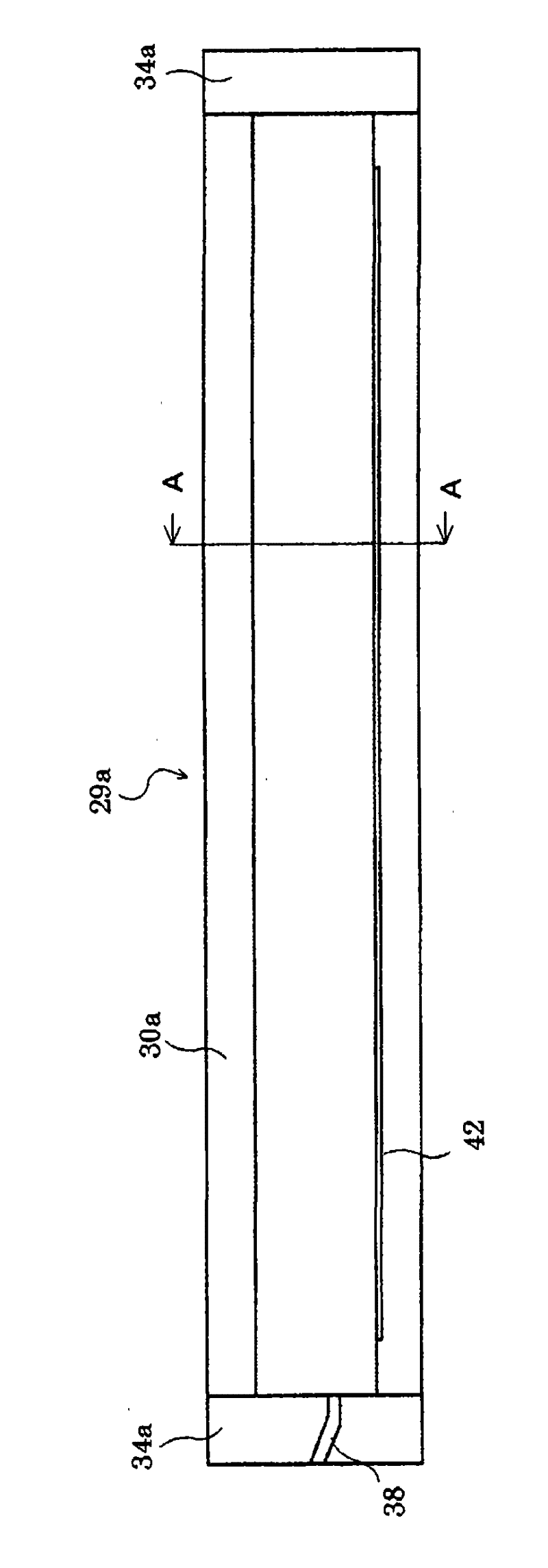
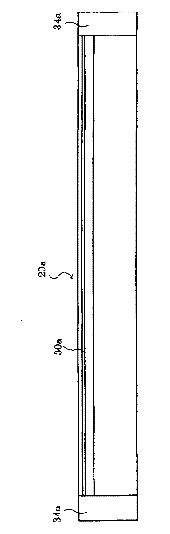
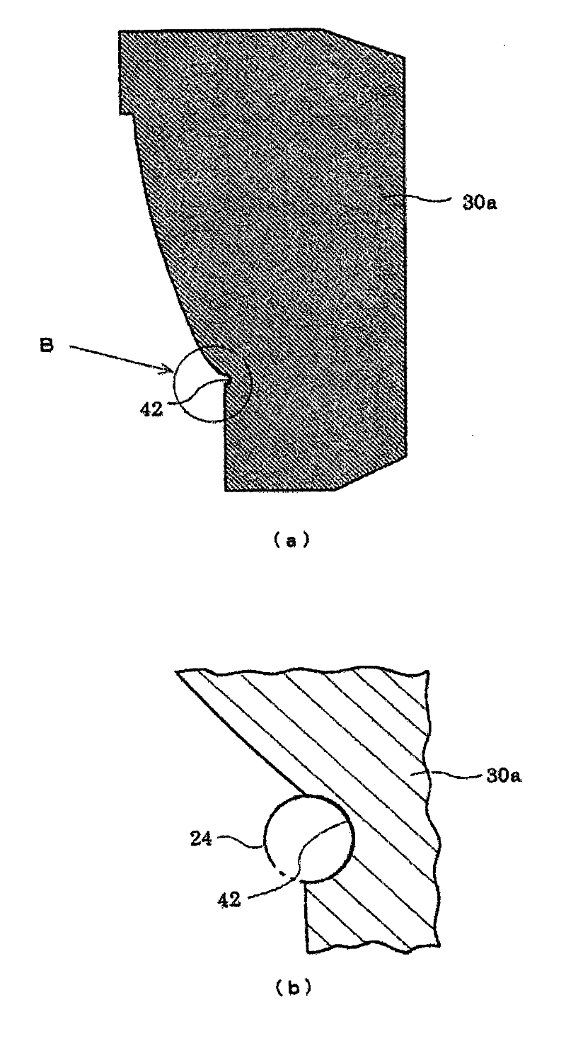
[0031] Figure 1 ~ Figure 3 It is a figure which shows the lower die of the liner molding die of one embodiment of the present invention, figure 1 is a top view, figure 2 is the main view, image 3 (a) is along figure 1 An enlarged sectional view of line A-A, image 3 (b) is an enlarged cross-sectional view of part B of (a). Figure 4 ~ Figure 6 It is a figure showing the upper die of this liner molding die, Figure 4 is a top view, Figure 5 is the main view, Figure 6 (a) is along Figure 4 An enlarged cross-sectional view of line C-C, (b) is an enlarged cross-sectional view of part D of (a). Figure 7 It is a figure which shows the state which combined the lower mold and the upper mold of this liner molding die 28, (a) is a transverse cross-sectional view, (b) is an enlarged cross-sectional view of the E part of this (a).

[0032] Such as Figure 7 As shown in (a), the liner molding die 28 of the present invention is a two-part mold, consisting of one parting d...


PUM


Abstract

This invention provides a pad molding mold which can ensure a necessary bonding area between a rubber material of a pressing pad (26) and a wire (24) and can prevent the occurrence of waving and bending of a wire (24) after molding. In a two-split mold for molding a pressing pad (26) having a pressing face (22) for pressing the outer peripheral surface of a fixing roller (16), a holding groove (42) for providing a wire (24) attached along one side of the pressing face (22) is provided in one split mold (29a) in the two-split mold. A plurality of protrusions (46) for pressing the outer surfaceof the wire (24) is intermittently provided in the longitudinal direction in the other split mold (29b), in the two-split mold, at its site opposed to the holding groove (42). The fixing roller (16) includes a pressing roller, and the pressing pad (26) includes a fixing pad.

Description

technical field [0001] The present invention relates to a pad molding die and a pad used for molding pads such as pressure pads and fixing pads used in fixing devices such as electronic copiers. Background technique [0002] In the past, for example, if Figure 9 As shown, in a fixing device 10 such as an electronic copier, the endless belt 14 pressed against the back by the pressure pad 12 is brought into pressure contact with the fixing roller 16, and the toner on the recording paper passing through the fixing area as the pressing area is brought into contact with each other. Agent fixing is well known (for example, refer to Patent Document 1). [0003] Figure 9 The shown fixing device 10 has a fixing roller 16 and an endless belt 14 in pressure contact therewith. The endless belt 14 is rotatably supported by a drive roller 15a, a driven roller 15b, and a tension roller 15c. Inside the endless belt 14, a pressure pad 12 formed of an elastic rubber material such as silic...

Claims


Application Information

Patent Timeline
Patent Type & Authority Patents(China)
IPC IPC(8): G03G15/20B29C33/12
CPCG03G15/20B29C33/12
Inventor 藤田刚士仓田博司山崎新司
Owner SWCC SHOWA CABLE SYST CO LTD
Why Eureka
Try Eureka