Lighting device and display device

a technology of a display device and a light source, applied in non-linear optics, instruments, optics, etc., can solve the problem of increasing the number of parts, and achieve the effect of preventing undulation of sheet-like optical components and limiting the increase in the number of parts

Active Publication Date: 2021-01-21
FUNAI ELECTRIC CO LTD
View PDF0 Cites 3 Cited by
  • Summary
  • Abstract
  • Description
  • Claims
  • Application Information

AI Technical Summary

Benefits of technology

[0006]One object is to provide a lighting device and a display device with which it is possible to prevent the undulation of a sheet-like optical member while limiting the increase in the number of parts.

Problems solved by technology

Thus, there is a problem that the number of parts increases.

Method used


Image

  • Lighting device and display device
  • Lighting device and display device
  • Lighting device and display device

Examples


first embodiment

[0021](Configuration of Liquid Crystal Television Apparatus)

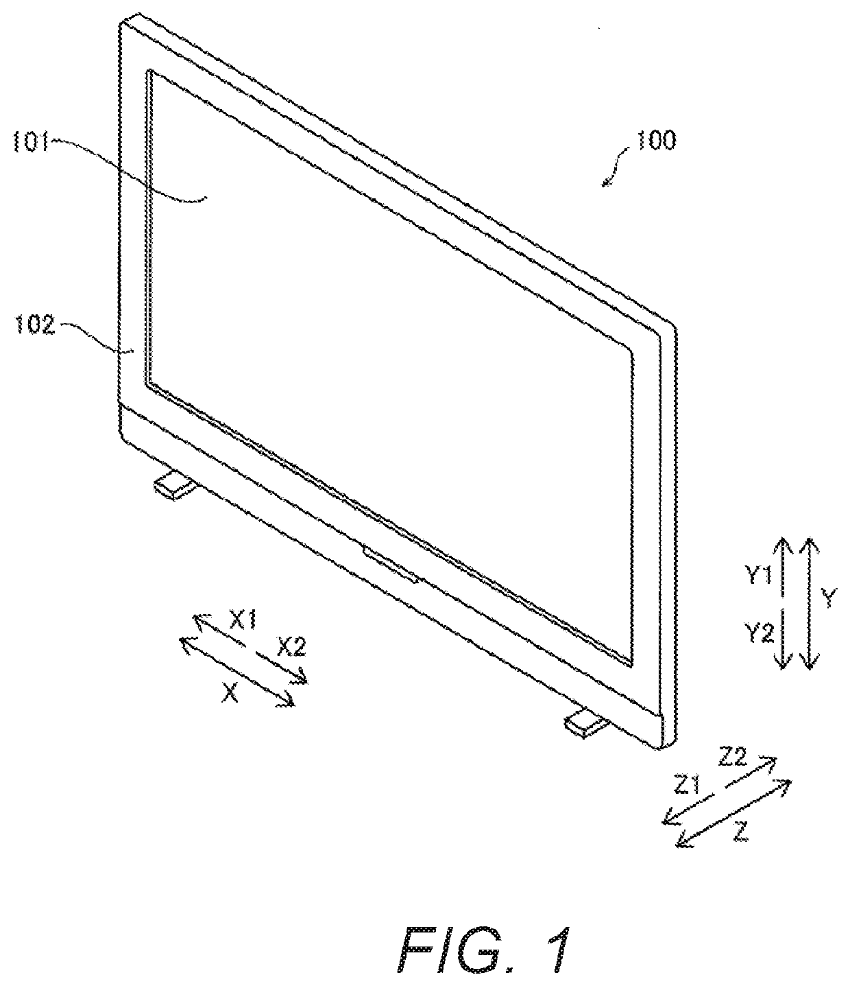
[0022]Referring to FIGS. 1 to 6, the configuration of a liquid crystal television apparatus 100 according to a first embodiment will be described. The liquid crystal television apparatus 100 is an example of the “display device” of the present disclosure.

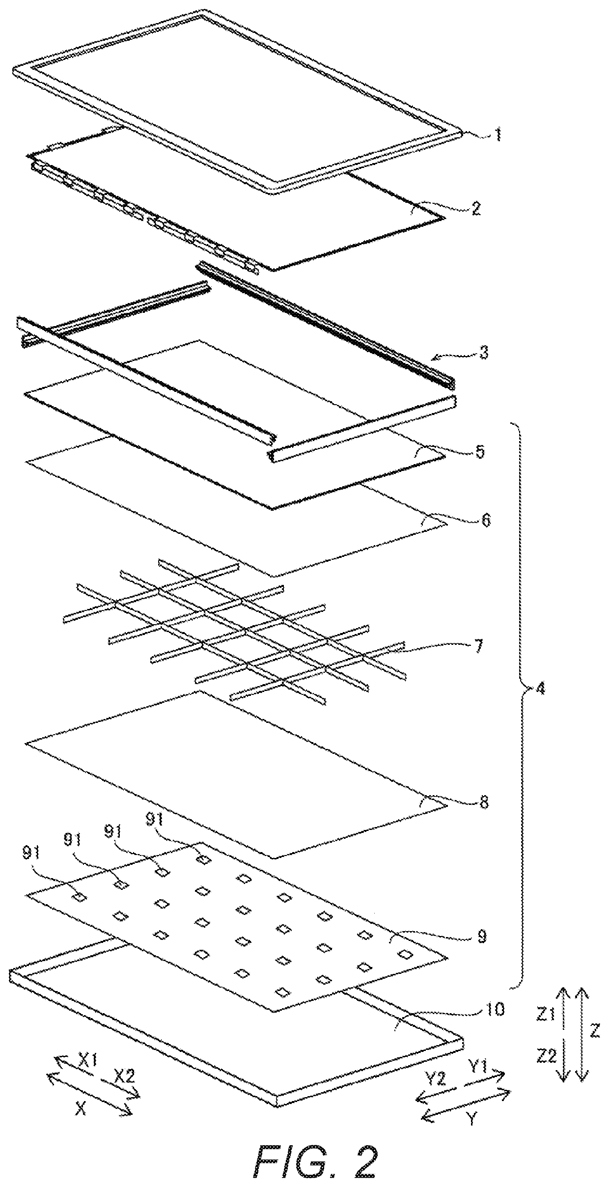
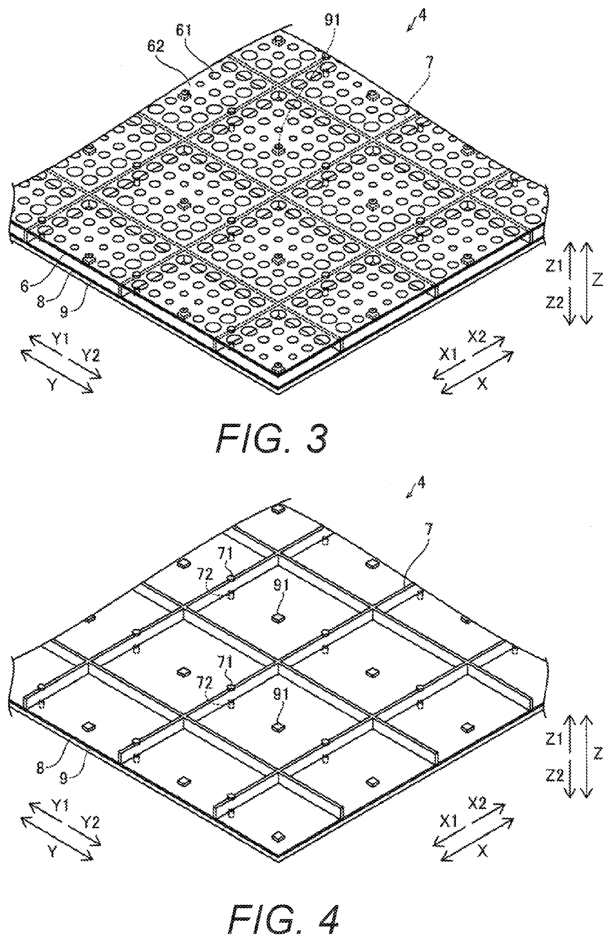
[0023]The liquid crystal television apparatus 100 according to the first embodiment includes, as shown in FIG. 1, a display section 101 and a housing 102. As shown in FIG. 2, the liquid crystal television apparatus 100 has a front housing 1, a display panel 2, an intermediate frame 3, a backlight 4, and a rear housing 10. The backlight 4 has a light diffusion plate 5, an optical member or optical sheet 6, a partition 7, a reflective sheet 8, and a substrate 9. The substrate 9 is provided with a plurality of light sources 91. The backlight 4 is an example of the “lighting device” of the present disclosure, and the reflective sheet 8 is an example of the “reflective member” o...

second embodiment

Effect of Second Embodiment

[0064]In the second embodiment, as in the first embodiment above, the optical member 6 is supported by the support portions 71 that are integrally provided with the partition 7 so as to protrude from the end portion of the partition 7 on the light diffusion plate 5 side (Z1 direction side) of the partition 7. With this configuration, the undulation of the sheet-like optical member 6 can be suppressed while the increase of the number of parts is suppressed.

[0065]Also, in the second embodiment, as described above, the partition 7 is integrally provided with the bottom surface 76 on the light source 91 side, and the bottom surface 76 is configured to reflect the light emitted from the light sources 91. With this configuration, there is no need to provide a separate reflective member that reflects light toward the optical member 6, and thus the increase in the number of parts can be effectively suppressed.

[0066]Other effects of the second embodiment are the sa...

third embodiment

Effect of Third Embodiment

[0074]In the third embodiment, as in the first embodiment above, the optical member 6 is supported by the support portions 71 that are integrally provided with the partition 7 so as to protrude from the end portion of the partition 7 on the light diffusion plate 5 side (Z1 direction side) of the partition 7. With this configuration, the undulation of the sheet-like optical member 6 can be suppressed while the increase of the number of parts is suppressed.

[0075]Other effects of the third embodiment are the same as in the first embodiment.


PUM

PropertyMeasurementUnit
thicknessaaaaaaaaaa
thicknessaaaaaaaaaa
thickness T2aaaaaaaaaa

Abstract

A lighting device includes a plurality of light sources, a light diffusion plate, a sheet-like optical member, and a partition. The light diffusion plate is arranged opposite the light sources. The light diffusion plate diffuses light from the light sources. The optical member is disposed between the light diffusion plate and the light sources. The optical member includes a transmitting part that transmits the light emitted from the light sources and a reflecting part that reflects the light emitted from the light sources. The partition is arranged between adjacent light sources. The optical member is held by a support portion that is integrally provided to the partition and protrudes from an end portion of the partition toward the light diffusion plate.

Description

CROSS-REFERENCE TO RELATED APPLICATIONS[0001]This application claims priority to Japanese Patent Application No. 2019-134024 filed on Jul. 19, 2019. The entire disclosure of Japanese Patent Application No. 2019-134024 is hereby incorporated herein by reference.BACKGROUNDField of the Invention[0002]The invention relates to a lighting device and a display device.Background Information[0003]Conventionally, display devices are known (see International Publication WO 2017 / 038082 (Patent Literature 1), for example).[0004]The above-described Patent Literature 1 discloses a display device that includes a light source, a sheet-like optical member that is disposed opposite the light source and includes a transmitting part that transmits the light emitted from the light source and a reflecting part that reflects the light emitted from the light source, and a reflective sheet that is disposed on the light source side with respect to the optical member and reflects the light emitted from the lig...

Claims


Application Information

Patent Timeline
Patent Type & Authority Applications(United States)
IPC IPC(8): G02F1/13357
CPCG02F1/133603G02F1/133608G02F1/133606G02F1/133605G02F2201/54G02F2201/46
Inventor KOBAYASHI, TOMOHIRO
Owner FUNAI ELECTRIC CO LTD
Why Eureka
Try Eureka