
Tracheal cannula fixing device

An endotracheal intubation and fixator technology, applied in the field of medical devices, can solve the problems of aggravating facial muscle tension and discomfort, the adhesive tape and the skin are not firmly adhered, and endangering the life safety of patients, etc. fixed effect

Inactive Publication Date: 2010-07-21
HOSPITAL ATTACHED TO QINGDAO UNIV
View PDF8 Cites 9 Cited by
  • Summary
  • Abstract
  • Description
  • Claims
  • Application Information

AI Technical Summary

Problems solved by technology

The traditional fixation method of tracheal intubation has been to first fix the tooth pad and tracheal intubation with adhesive tape, and then directly paste it on the cheeks on both sides of the patient with adhesive tape. Usually, the adhesive tape is fixed on the cheeks and nose, which are easily affected by the sweat glands of the skin. and oily secretions, the adhesive tape and the skin are not firmly adhered, and there is still a large range of motion after the endotracheal intubation is fixed, especially when the patient is agitated or changes the position, it is more likely to cause catheter displacement and detachment, which endangers the patient safety
When the adhesive tape is used for fixation, the stretching can be too tight, which can easily cause discomfort to the patient, and it looks unsightly from the outside; the adhesive tape stretches the cheeks and aggravates the tension and discomfort of the facial muscles, which can stimulate the skin and cause inflammation or epidermal ulceration , leading to secondary infection, causing additional pain to the patient, and fixing the adhesive tape requires the cooperation of two people to complete, and the operation is complicated

Method used


Image

  • Tracheal cannula fixing device
  • Tracheal cannula fixing device
  • Tracheal cannula fixing device

Examples


Embodiment Construction

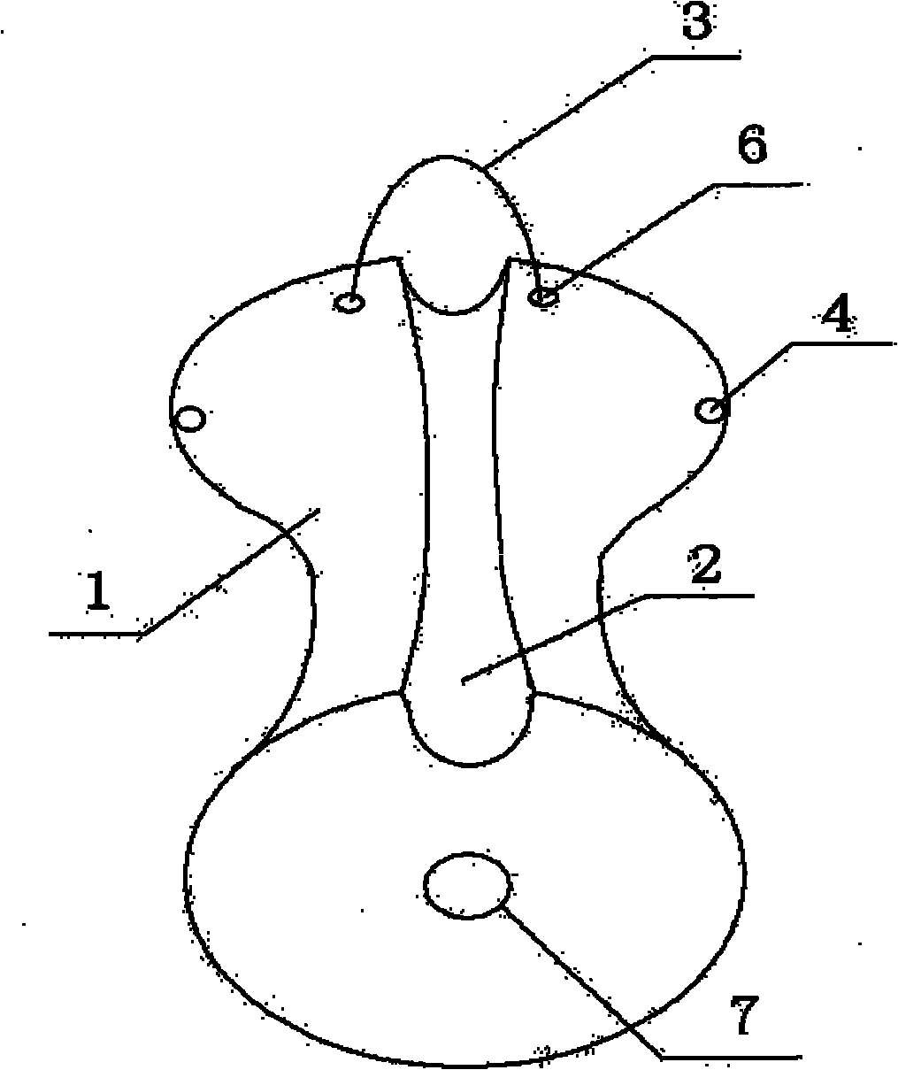
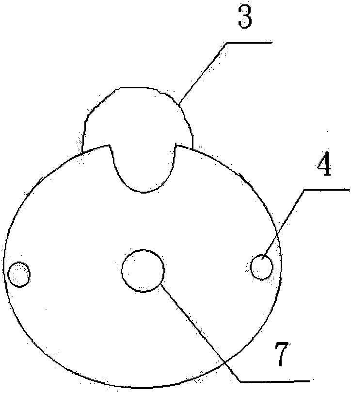
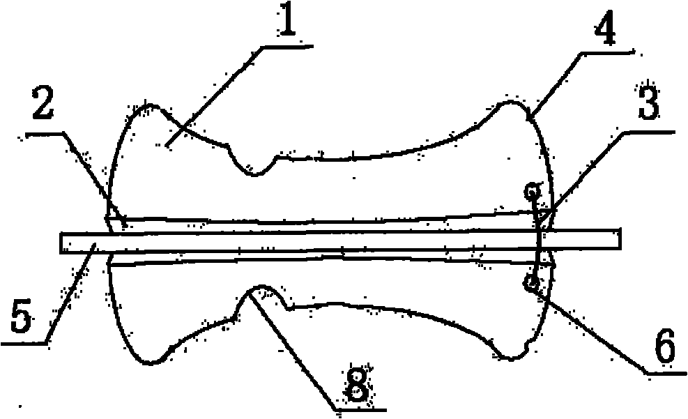
[0014] Such as figure 1 , 2 , the technical solution of the present invention includes a tracheal intubation tube 5 and a mouthpiece main body 1 with a through hole 7 in the axial direction, and is characterized in that it also includes a trachea embedded in the axial direction of the outer surface of the mouthpiece main body 1 A groove 2 of the intubation tube 5 is provided with a pair of jacks 6 on one end of the mouthpiece main body 1, and a spring clip 3 is inserted in the jacks 6, and a pair of jacks 6 are provided on the mouthpiece main body 1. There are two tie holes 4 symmetrically arranged on both sides.

[0015] Such as figure 1 , 3 The main body 1 of the mouthpiece of the present invention is in the shape of a waist drum with thick ends and a thin middle. The length of the mouthpiece main body 1 is 70-80 mm, the diameter of the mouth-containing end is 25 mm, and the diameter of the other end is 30 mm.

[0016] Such as image 3 , There are two symmetrical groove...


PUM

PropertyMeasurementUnit
Lengthaaaaaaaaaa
Diameteraaaaaaaaaa

Abstract

The invention relates to a tracheal cannula fixing device, which comprises a tracheal cannula and a mouth piece main body which is provided with a through hole in the axial direction, and is characterized by also comprising a groove which is arranged on the outer side surface of the mouth piece main body in the axial direction and is used for holding the tracheal cannula, wherein one end of the mouth piece main body is provided with a pair of jacks, a spring clip is plugged inside the jack, and two fastening holes are symmetrically arranged at two sides of the pair of jacks of the mouth piece main body. Two symmetric grooves are arranged on the occlusion part of the mouth piece main body; and the mouth piece main body is of a waistdrum shape with large ends and narrow middle part, the length of the mouth piece is 70 to 80 mm, the diameter of the occlusion end is 25 mm, and the diameter of the other end is 30 mm. The tracheal cannula fixing device has simple structure and convenient operation, can better conform to the dissecting physical curve of the mouth, and has the advantages that the fixture is firm, the skin of the patient can be protected, the pain of the patient can be alleviated, the fixing success rate of the tracheal cannula can be improved, and the like.

Description

[0001] technology field. [0002] The invention relates to the field of medical instruments, in particular to a tracheal intubation fixer. Background technique [0003] The tracheal intubation inserted into the patient's trachea through the oral or nasal cavity has played an important role in the rescue of critically ill patients. It is the most commonly used medical device in clinical first aid resuscitation, rescue of respiratory muscle paralysis, surgical anesthesia and open airway. The safe fixation of the endotracheal tube is an important guarantee for successful intubation. The traditional fixation method of tracheal intubation has been to first fix the tooth pad and tracheal intubation with adhesive tape, and then directly paste it on the cheeks on both sides of the patient with adhesive tape. Usually, the adhesive tape is fixed on the cheeks and nose, which are easily affected by the sweat glands of the skin. and oily secretions, the adhesive tape and the skin are not...

Claims


Application Information

Patent Timeline
IPC IPC(8): A61M16/04
Inventor 赵春玲郭鹏菊石新艳孙爱莲赵云王俊
Owner HOSPITAL ATTACHED TO QINGDAO UNIV
Learn More