Novel gas-liquid two-phase feeding distribution structure

A feeding distribution pipe and feeding technology, applied in the chemical industry, can solve problems affecting uniformity, affecting liquid flow and gas-liquid separation, reducing tower separation accuracy and operational stability, etc., to reduce operating energy consumption and improve separation and distribution effect, the effect of improving separation efficiency

Active Publication Date: 2012-07-04
CHINA PETROCHEMICAL CORP +1
View PDF2 Cites 0 Cited by
  • Summary
  • Abstract
  • Description
  • Claims
  • Application Information

AI Technical Summary

Problems solved by technology

[0007] However, these two feed types are only suitable for pure liquid phase feeds
When gas-liquid two-phase feed, these two feeding methods will affect the liquid flow and gas-liquid separation in the downcomer to varying degrees, and affect the uniformity of gas-liquid distribution above the tower feed plate, reducing the separation of the tower Accuracy and operational stability

Method used


Image

  • Novel gas-liquid two-phase feeding distribution structure
  • Novel gas-liquid two-phase feeding distribution structure
  • Novel gas-liquid two-phase feeding distribution structure

Examples


Embodiment 1

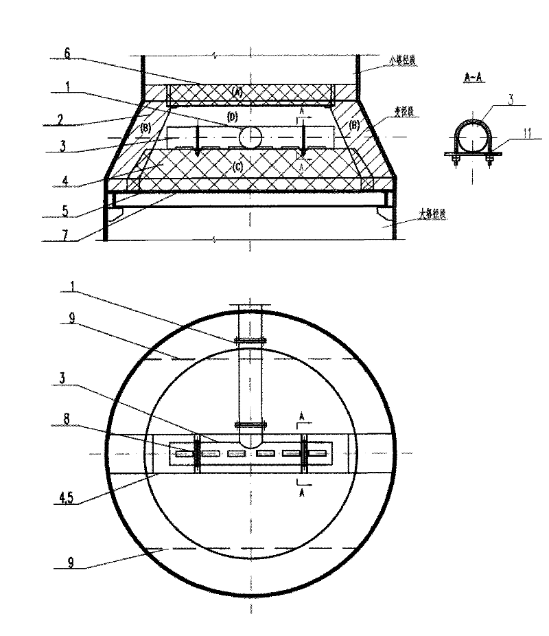
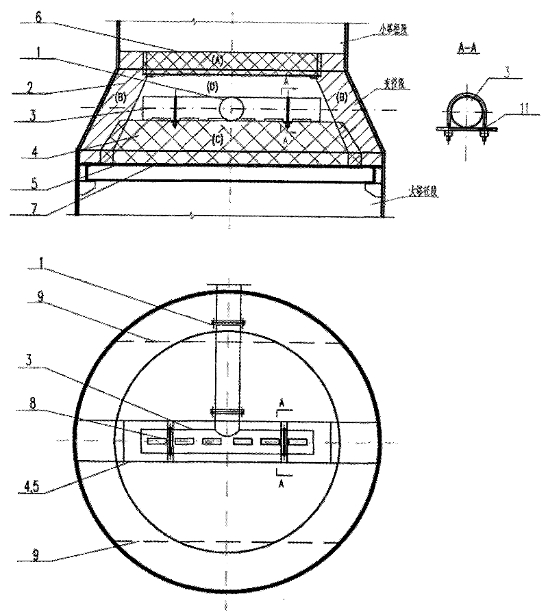
[0020] Example 1 as figure 1 As shown, a gas-liquid two-phase feed distribution structure used in the stabilizing tower, the stabilizing tower consists of small tower diameter section, variable diameter section and large tower diameter section from top to bottom, The material distribution structure is located in the variable diameter section of the stabilizing tower, including the upper tray 6, the upper downcomer 2, the open downcomer 4, the lower liquid tray 5, the lower tray 7, the feed main pipe 1 and the feed Distribution pipe 3.

[0021] The upper floor tray 6 is located at the bottom of the small tower diameter section of the stable tower, and is a double overflow tray; the upper floor downcomer 2 is located below the upper floor tray 6, and the lower floor tray 7 is located at the bottom of the stable tower. On the upper part of the large tower diameter section, on both sides of the lower tray near the tower wall are the downcomers 9 on both sides of the lower floor, ...

Embodiment 2

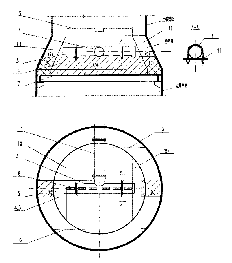
[0026] Example 2 as figure 2 As shown, its difference from Embodiment 1 is that the upper downcomer and the lower liquid receiving pan 5 are vertical at 90 degrees. The upper layer downcomer is the downcomer 10 on both sides of the upper layer, which is downward along both sides of the tower wall at the variable diameter section; an open downcomer 4 is separately arranged above the liquid receiving plate 5 in the middle of the lower layer; the downcomer 4 on both sides of the upper layer The two ends of the pipe 10 and the open downcomer 4 are sealed and penetrated, and the sealing and penetration here is realized by the following method: after the downcomer 10 on both sides of the upper layer intersects with the two ends of the open downcomer 4, the figure 2The part outside the middle C area is closed, that is to say, the intersections of the two ends of the open downcomer 4 and the two lower ends of the downcomer 10 on both sides of the upper layer are respectively fused t...


PUM


Abstract

The invention provides a gas-liquid two-phase feeding distribution structure for a stabilizing tower, which belongs to the field of chemical engineering. The gas-liquid two-phase feeding distribution structure comprises an upper-layer tower plate, an upper-layer downcomer duct, an open downcomer duct, a lower-layer liquid receiving pan, a lower-layer tower plate, a feeing main pipe and a feeding distribution plate; the upper-layer downcomer duct and the open downcomer duct form a hollow gantry structure; liquid in the upper-layer tower plate is subjected to gas-liquid separation in the upper-layer downcomer duct and flows into the open downcomer duct; feeding materials are subjected to gas-liquid separation in the open downcomer duct; gas rises to be mixed with a gas phase from the lower-layer tower plate in a gantry space and then enters the upper-layer tower plate; and the liquid and upper-layer downcomer from two sides are mixed and then are distributed on the lower-layer tower plate. The invention successfully solves the problem of the feeding distribution in a naphtha stabilizing tower of an oil refinery, improves the separation and distribution efficiencies of the gas-liquidtwo-phase feeding, improves the separation efficiency of the tower, reduces the energy consumption for operation and effectively utilizes the reducing space of a tower body.

Description

technical field [0001] The invention belongs to the field of chemical industry, and in particular relates to a gas-liquid two-phase feed distribution structure used in a stabilizing tower. Background technique [0002] The feed of the naphtha stabilization tower in the refinery generally adopts pure liquid phase feed, and the feed position is located in the variable diameter section of the stabilization tower. Basically single overflow. [0003] With the rapid development of my country's economy and the continuous expansion of petrochemical equipment scale, the requirements for energy saving and consumption reduction of equipment are getting higher and higher. What follows is that the gas-liquid two-phase feeding condition often occurs after the feed of the naphtha stabilization tower in the refinery is fully exchanged; in addition, due to the increase in equipment scale, the stabilization tower often adopts double overflow flow Type, the feeding position is in the variabl...

Claims


Application Information

Patent Timeline
Patent Type & Authority Patents(China)
IPC IPC(8): B01D3/20B01D53/18
Inventor 王秋萍袁毅夫
Owner CHINA PETROCHEMICAL CORP
Why Eureka
Try Eureka