Crystal grain angle correction method applied to chip separating system

A sorting system and angle correction technology, applied in sorting and other directions, which can solve the problems of reducing the speed of chip sorting, difficulty in precise positioning of grains, and affecting the speed of grain angle correction.

Inactive Publication Date: 2010-07-21
DG HUST MFG ENG RES INST +1
View PDF0 Cites 16 Cited by
  • Summary
  • Abstract
  • Description
  • Claims
  • Application Information

AI Technical Summary

Problems solved by technology

The correction method of this crystal grain angle, because the angle correction of any crystal grain in the feeding area all needs to rotate the whole chip film, causes the position of all other crystal grains on this chi

Method used


Image

  • Crystal grain angle correction method applied to chip separating system
  • Crystal grain angle correction method applied to chip separating system
  • Crystal grain angle correction method applied to chip separating system

Examples


Embodiment 1

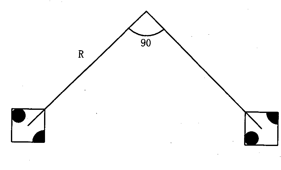
[0082] An embodiment of a grain angle correction method applied to a chip sorting system of the present invention is as follows figure 1 Shown is a flow chart of a method of the present invention.

[0083] Specifically, a grain angle correction method applied to a chip sorting system, wherein the chip sorting system includes an image recognition system, a chip feeding table, a grain transfer mechanism and an arrangement area, and the image recognition system includes A high-speed camera, the chip feeding platform includes an XY cross platform, a thimble and a Z-axis rotating platform, wherein the method includes the following steps:

[0084] Step 101, setting the deflection range parameter of the allowable grain angle in the chip sorting system; wherein, this parameter can select different deflection range values ​​according to the needs of the user, and the deflection range of the allowable grain angle commonly used in the industry It is -15°~+15° or -9°~+9°.

[0085] Step ...

Embodiment 2

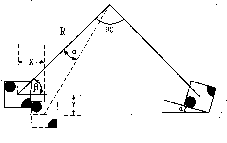
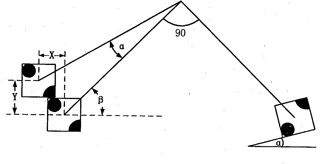
[0111] An embodiment of a grain angle correction method applied to a chip sorting system of the present invention is as follows figure 2 Shown is another method flow chart of the present invention.

[0112] Specifically, a grain angle correction method applied to a chip sorting system, wherein the chip sorting system includes an image recognition system, a chip feeding table, a grain transfer mechanism and an arrangement area, and the image recognition system includes A high-speed camera, the chip feeding platform includes an XY cross platform, a thimble and a Z-axis rotating platform, wherein the method includes the following steps:

[0113] Step 201, setting the allowable deflection range parameters of the grain angle in the chip sorting system.

[0114] Step 202, selecting one of the dies on the chip film as the target die.

[0115] Step 203, drive the XY cross platform of the chip feed table to move the target die to the recognition area of ​​the lens of the high-speed ...


PUM


Abstract

The invention relates to a crystal grain angle correction method applied to a chip separating system, which mainly comprises the following steps: judging a deflection angle of target crystal grains; driving a swinging arm of a crystal grain conveying mechanism to rotate 90 degrees minus alpha when the deflection angle alpha of the target crystal grains is a positive number, simultaneously executing the difference-alpha deflection angle position compensation on an arrangement region, and placing the target crystal grains into the arrangement region; driving the swinging arm of the crystal grain conveying mechanism to rotate 90 degrees plus alpha when the deflection angle alpha of the target crystal grains is a negative number, simultaneously executing the multi-alpha deflection angle position compensation on the arrangement region, and placing the target crystal grains into the arrangement region; and driving the swinging arm of the crystal grain conveying mechanism to rotate 90 degrees when the deflection angle alpha of the target crystal grains is zero, and directly placing the target crystal grains into the arrangement region. The invention combines the rotation movement of the crystal grain conveying mechanism and the translational movement of the arrangement region for compensating the angle deflection of the crystal grains, carries out parallel dispatch between the position compensation of a material supply region and the arrangement region, and realizes the automatic correction of the crystal grain angle under the condition of not reducing the conveying speed.

Description

technical field [0001] The invention relates to the field of LED chip sorting, in particular to a crystal grain angle correction method applied to a chip sorting system. Background technique [0002] Usually, in the sorting process of LED chips, it is required to neatly arrange the crystal grains on the chip film in the form of square sheets according to the type. However, it is difficult to keep all the crystal grains absolutely neatly aligned after the chip film is cut, poured, and expanded. If the position of the grain is only irregular, it can be realized by translation correction, which is relatively easy to realize in terms of motion control; if the grain has an angular deviation, it needs to be realized by rotation correction. Since the correction of any crystal grain needs to rotate the entire chip film, this will cause the positions of all other crystal grains on the chip film to change, which brings great difficulties to the precise positioning of subsequent cryst...

Claims


Application Information

Patent Timeline
IPC IPC(8): B07C5/02
Inventor 李斌吴涛黄禹李海洲龚时华王龙文林康华
Owner DG HUST MFG ENG RES INST
Why Eureka
Try Eureka