
Metal mould containing sandmold insert and application thereof in tilted casting

A technology of metal molds and inserts, which is applied to casting molding equipment, metal processing equipment, casting molds, etc., can solve problems such as difficulty in improving quality levels, increased energy consumption, increased costs, and increased load on tilting machines, so as to simplify mold design , long mold life and low loss of metal mold

Active Publication Date: 2012-07-04
广东鸿特精密技术肇庆有限公司
View PDF0 Cites 0 Cited by
  • Summary
  • Abstract
  • Description
  • Claims
  • Application Information

AI Technical Summary

Problems solved by technology

However, the following two problems are difficult to solve in the production of automotive cylinder heads, discs, and shell parts: first, the structure of automotive cylinder heads, discs, and shell parts is complex, and there are often cavities and concave corners. The use of the core-pulling mechanism increases the difficulty of mold design, and also increases the load of the tilting machine, significantly increasing energy consumption and cost, which greatly restricts the ability to produce this type of parts; second, the mold is closed during the metal mold tilting casting process. The air permeability is poor, and the gas wrapped by the molten metal during the turning process is difficult to discharge out of the mold cavity, resulting in pore defects, resulting in a high casting rejection rate and difficult to improve the quality level

Method used


Image

  • Metal mould containing sandmold insert and application thereof in tilted casting
  • Metal mould containing sandmold insert and application thereof in tilted casting
  • Metal mould containing sandmold insert and application thereof in tilted casting

Examples


Embodiment Construction

[0022] The present invention will be further described through the following examples in conjunction with the accompanying drawings, but the embodiments of the present invention are not limited thereto.

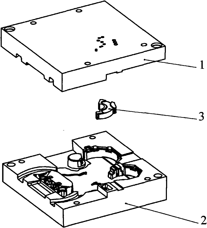
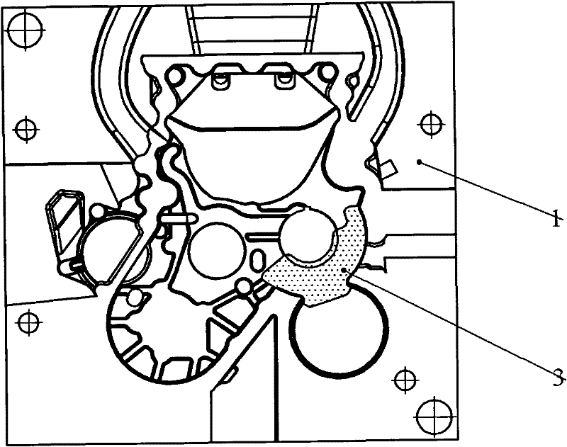
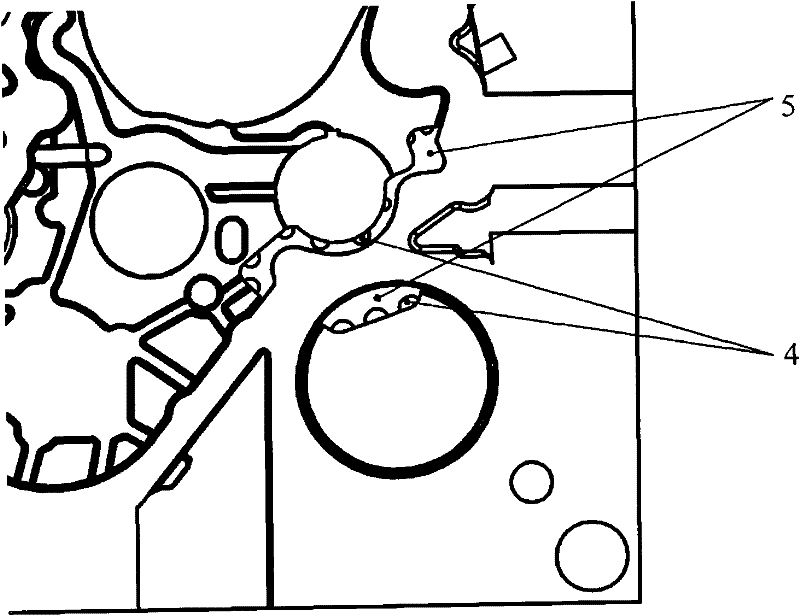
[0023] The structure of the metal mold containing sand inserts used in the production of castings in this embodiment mainly includes a metal upper mold 1, a metal lower mold 2, a sand mold insert 3, a metal mold vent 4, and an insert support seat 5. figure 1 and figure 2 The positional relationship between the sand mold insert 3 and the metal upper mold 1 and the metal lower mold 2 is given. Since there is a cavity in the casting blank 6, the sand mold insert 3 needs to be installed at the cavity position, and after process analysis, this position also produces air holes The position of the defect, so the sand mold insert 3 is not only used as the core, but also used to discharge the residual gas in the cavity; the shape of the sand mold insert 3 is determined by the followi...


PUM


Abstract

The invention discloses a metal mould containing a sandmold insert and an application thereof in tilted casting. The metal mould containing the sandmold insert comprises a metal mould cavity, a casting system, a clamping mechanism, the sandmold insert, metal mould air vents and an insert supporting seat; the forming surface of the sandmold insert is in accordance with the outline of the outer surface of a raw casting, the mould contact surface of the sandmold insert is in accordance with the outline of the insert supporting seat formed by inward processing of the sandmold insert; the metal mould air vents, which are evenly distributed along the contact surface of the sandmold insert and a metal upper mould, are contacted with the sandmold insert and communicated with outer atmosphere, theaperture thereof is 5mm-20mm, and the center distance between vents is 15mm-30mm. In the invention, the sandmold insert is utilized to replace a core puller of the metal mould, thereby simplifying mould design and overcoming the problem of difficult exhaustion of the metal mould. The casting utilizing the invention has compact texture and high yield, and has particularly notable advantages in theproduction of cylinder covers, chassis, shells and the like used for automobiles.

Description

technical field [0001] The invention belongs to the technical field of casting, and in particular relates to a metal mold containing sand mold inserts and its application in tilting casting. It is mainly suitable for casting all kinds of auto parts with complex structures and large sizes, such as cylinder heads, discs, shells, etc. Background technique [0002] Traditional sand mold gravity casting has disadvantages such as low production efficiency, difficult control of process conditions, low casting quality and poor mechanical properties in the production of auto parts cylinder heads, discs, shells and other products with complex structures and high quality requirements. , and gradually eliminated. The metal mold gravity casting process can produce castings with dense structure and good mechanical properties, but it is difficult to design the pouring scheme when producing large and complex castings: if the bottom injection type is used, the flow of molten metal will be t...

Claims


Application Information

Patent Timeline
Patent Type & Authority Patents(China)
IPC IPC(8): B22C9/00B22C9/06
Inventor 李四娣张十中罗金祺周智清
Owner 广东鸿特精密技术肇庆有限公司
Learn More