Spherical hinge disc suspension type connection device of converter ring and furnace shell

A converter support ring and connecting device technology, applied in the direction of manufacturing converters, etc., can solve the problems of difficult installation and many connection points, and achieve the effects of simple structure, reliable connection, and avoidance of local overload.

Inactive Publication Date: 2011-09-28
WISDRI ENG & RES INC LTD
View PDF1 Cites 0 Cited by
  • Summary
  • Abstract
  • Description
  • Claims
  • Application Information

AI Technical Summary

Problems solved by technology

In addition, there are too many connection points in this connection method, and the installation is difficult

Method used


Image

  • Spherical hinge disc suspension type connection device of converter ring and furnace shell
  • Spherical hinge disc suspension type connection device of converter ring and furnace shell
  • Spherical hinge disc suspension type connection device of converter ring and furnace shell

Examples


Embodiment 1

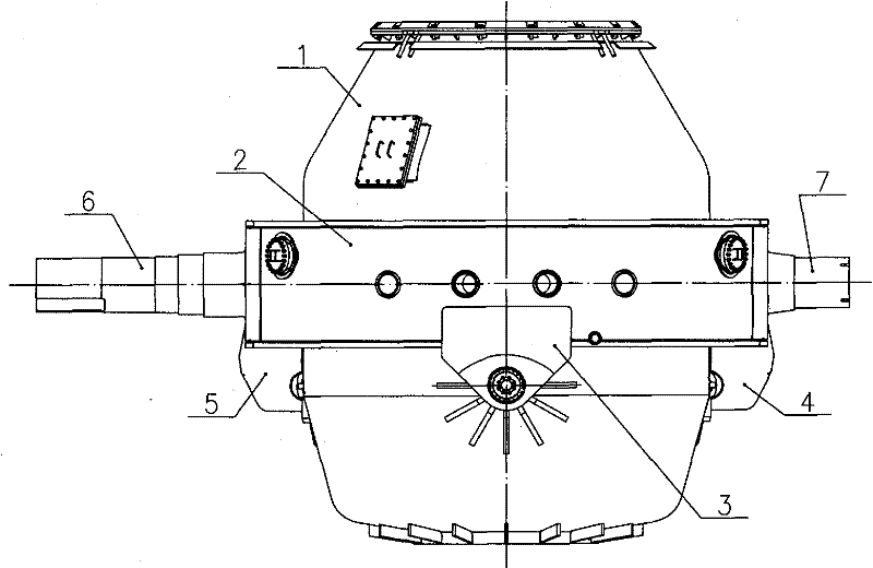
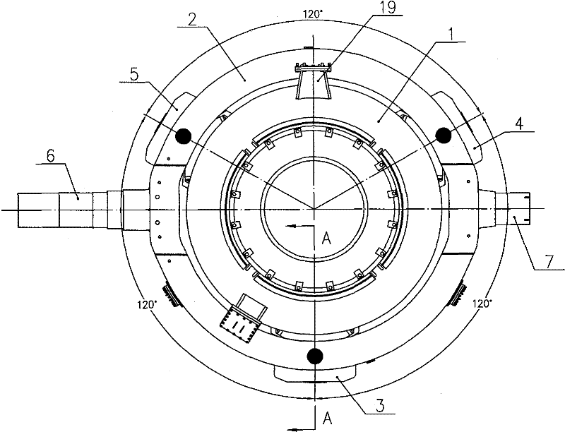
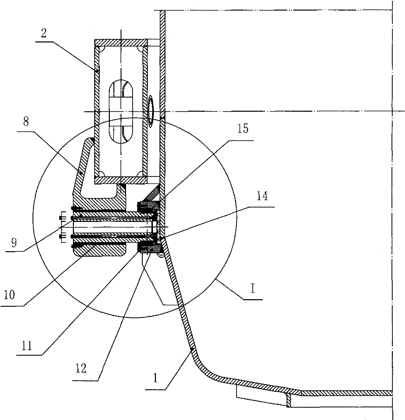
[0032] Such as figure 1 , figure 2 , image 3 , Figure 4 , Figure 5 , Image 6 As shown, the connecting device of the spherical hinge suspension disc type converter support ring and the furnace shell is composed of three connecting units (or called spherical hinge sliding rod mechanisms) (namely the first connecting unit 3, the second connecting unit 4, the second connecting unit Three connection units 5);

[0033] Each connection unit includes ear seat 8, support shaft 9, sliding sleeve 10, gland 11, support ring 12, rib plate 13, end cover 14, ball joint bearing 15, and ear seat 8 is fixedly connected with support ring 2 (such as welding ), the lug 8 is provided with a sliding sleeve through hole, the sliding sleeve 10 is located in the sliding sleeve through hole, the sliding sleeve 10 is fixedly connected with the lug 8 (such as connected by bolts), and the outer end of the support shaft 9 penetrates the sliding sleeve 10 (the support shaft 9 can slide along the a...

Embodiment 2

[0038] Such as Figure 7 As shown, there are four connecting units (namely the first connecting unit 3, the second connecting unit 4, the third connecting unit 5, and the fourth connecting unit 21), which are evenly distributed and form an angle of 90 degrees between them. The included angle between the line connecting the connecting unit and the center of the converter and the axis of the trunnion (the axis of the trunnion 6 at the transmission end and the axis of the supporting trunnion 7 ) is 25° to 45°. In the vertical direction of the furnace shell, the connection unit is arranged at the center of gravity of the furnace shell and refractory materials inside the furnace shell.


PUM


Abstract

The invention relates to a connection device of a converter ring and a furnace shell, in particular to a spherical hinge disc suspension type connection device of the converter ring and the furnace shell. The connection device is characterized by consisting of 3 to 4 connection units. Each connecting unit comprises a lug, a support shaft, a sliding sleeve, a support ring, and a spherical hinge bearing, wherein the lug is fixedly connected with the converter ring and provided with a through hole for the sliding sleeve which is positioned in the through hole and is fixedly connected with the lug; the external end of the support shaft is inserted into the sliding sleeve; the internal end of the support shaft is fixedly connected with the internal ring of the spherical hinge bearing; and the external ring of the spherical hinge bearing is fixedly connected with the support ring which is fixedly connected with the furnace shell. The connection device has the characteristics of simple structure, high reliability, free maintenance, and no additional stress generation in operation process of the converter.

Description

technical field [0001] The invention relates to a connection device between a converter support ring and a furnace shell. The device is used in the technical field of converter steelmaking equipment, or the technological requirements of other similar smelting furnaces. Background technique [0002] The connection device between the converter shell and the supporting ring is an important part of the converter equipment, through which the supporting ring can drive the furnace shell to rotate to complete the operations of charging, sampling, temperature measurement, slag tapping and steel tapping in the steelmaking process. Therefore, the connection device should be able to ensure that the furnace shell load can be transferred to the support ring when the converter is at any tilting position, and maintain the correct position of the furnace shell in the support ring, and at the same time be able to adapt to the expansion of the furnace shell in the axial and radial directions. ...

Claims


Application Information

Patent Timeline
Patent Type & Authority Patents(China)
IPC IPC(8): C21C5/46
Inventor 盛正平严国平盛汉桥邵远敬杜斌叶理德刘斌奇张文宋晓燕徐时栋陶有能李贝田兆营
Owner WISDRI ENG & RES INC LTD
Why Eureka
Try Eureka