Supercharge Your Innovation With Domain-Expert AI Agents!

A device and method for measuring modulation transfer function

A technique of modulating transfer function and measuring direction, which is applied in the direction of testing optical performance, etc. It can solve the problems of inaccurate registration of fringe image and image detector pixel, inability to measure MTF value, and reduction of pixel number, etc., to achieve design and production Convenience, simple structure, and the effect of reducing the influence of accuracy

Inactive Publication Date: 2011-12-21
SUZHOU UNIV
View PDF3 Cites 0 Cited by
  • Summary
  • Abstract
  • Description
  • Claims
  • Application Information

AI Technical Summary

Problems solved by technology

[0006] This technical solution uses a resolution board with a rectangular change in the gray scale of the graphic to replace the resolution board with a sinusoidal change in the gray scale of the graphic that is difficult to design and process, and realizes the measurement of the modulation transfer function of the camera, but there are still two deficiencies in the following aspects: (1) The spatial resolution board contains multiple resolution graphics from low frequency to high frequency. When the spatial frequency increases, the number of pixels corresponding to the imaging range of a single resolution fringe to the detector image plane decreases.
The inaccurate registration of the fringe image and the image detector pixel will cause measurement errors, making the measured value of MTF smaller than the actual value
(2) This method can only measure the MTF values ​​in the horizontal and vertical directions, and cannot measure the MTF values ​​in other directions

Method used


Image

  • A device and method for measuring modulation transfer function
  • A device and method for measuring modulation transfer function
  • A device and method for measuring modulation transfer function

Examples


Embodiment 1

[0027] This embodiment provides a device and method for measuring the modulation transfer function of an optoelectronic instrument.

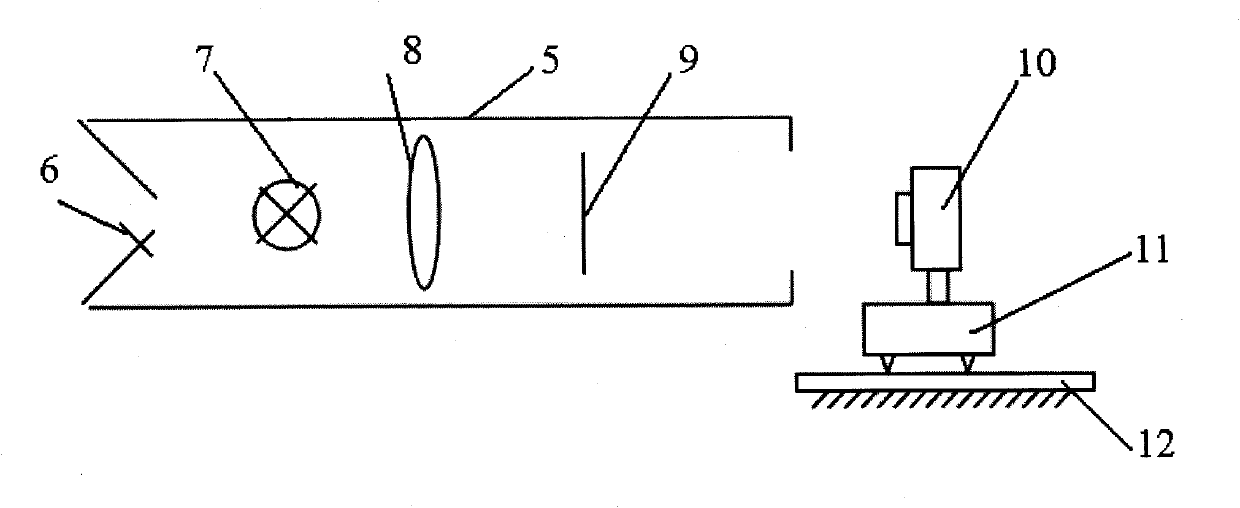
[0028] See attached figure 2 , which is a structural schematic diagram of a modulation transfer function measurement device provided in this embodiment. Before the measurement, the measuring instrument needs to be calibrated: the light source 7 is placed at the focal point of the collimator 8, the light source is turned on, the light emitted by it passes through the collimator, and parallel light with uniform intensity is output; the resolution plate 9 is placed in the collimator On the bracket in 5, it is located in the center of the cross-section of the collimator, which can be realized by observing through the eyepiece 6; Adjust the height of the two-dimensional translation stage so that the center of the entrance pupil of the photoelectric instrument to be tested is at the same height as the center of the resolution plate in the collimator...


PUM


Abstract

The invention discloses a device and method for measuring modulation transfer function. The resolution plate of the device is placed on the bracket of the collimator, located in the center of the cross-section of the collimator, and its outer frame is a square, and the graphics on the resolution plate are concentric, bright and dark annular stripes with different spacing and width. . The measurement method takes the azimuth θ of the required measurement direction as the center, and continues the micro angles in the left and right directions of the azimuth as the processing area, and the spatial direction and spatial frequency of the resolution plate in the processing area The image of the stripe area is measured, and after data processing, the maximum and minimum values ​​of the gray value of the image are counted to obtain the contrast of the image within the range of the required measurement direction, and the value of the modulation transfer function is calculated. The invention adopts the annular resolution pattern of the resolution plate, not only can measure the MTF value in the horizontal and vertical directions of the photoelectric instrument, but also can measure the MTF value in any spatial direction.

Description

technical field [0001] The invention relates to a method and a device for measuring the modulation transfer function of optical devices or photoelectric instruments. Background technique [0002] The modulation transfer function (MTF) reflects the degree of image contrast attenuation during the imaging process at different spatial frequencies, and is a physical quantity used to evaluate the imaging performance of optoelectronic instruments and optical lenses. [0003] Due to the different measurement principles, traditional instruments can only measure the modulation transfer function of optical devices or optical instruments alone. The data processing of the traditional method requires time-frequency conversion, which is restricted by data processing overhead and precision. The measurement method without data time-frequency conversion has high requirements for sample design and production. When the graphic spatial frequency of the resolution board is high, measurement erro...

Claims


Application Information

Patent Timeline
Patent Type & Authority Patents(China)
IPC IPC(8): G01M11/02
Inventor 陈宇恒陈新华周建康季轶群相春昌沈为民
Owner SUZHOU UNIV
Features
  • R&D
  • Intellectual Property
  • Life Sciences
  • Materials
  • Tech Scout
  • Unparalleled Data Quality
  • Higher Quality Content
  • 60% Fewer Hallucinations
Learn More