Thrust reverser with a system for braking the actuators

A thrust reverser, reverser technology, applied in the direction of machines/engines, jet propulsion devices, etc., can solve problems such as opening the plane and crashing

Inactive Publication Date: 2010-07-21
AIRCELLE
View PDF2 Cites 8 Cited by
  • Summary
  • Abstract
  • Description
  • Claims
  • Application Information

AI Technical Summary

Problems solved by technology

[0011] These locking systems also meet stringent safety standards, especially after the Lauda crash, in which it was discovered that an unwelcome opening of the thrust reverser system during flight led to the loss of the plane

Method used


Image

  • Thrust reverser with a system for braking the actuators
  • Thrust reverser with a system for braking the actuators
  • Thrust reverser with a system for braking the actuators

Examples


Embodiment Construction

[0037] Before describing embodiments of the present invention in detail, it is important to emphasize that the described system is not limited to any particular type of inverter.

[0038] Although it has been shown in the form of an electrically actuated cascade type reverser, it is of course possible to apply the principles of the invention to pneumatically or hydraulically actuated systems as well as other types of reversers, e.g. to the device.

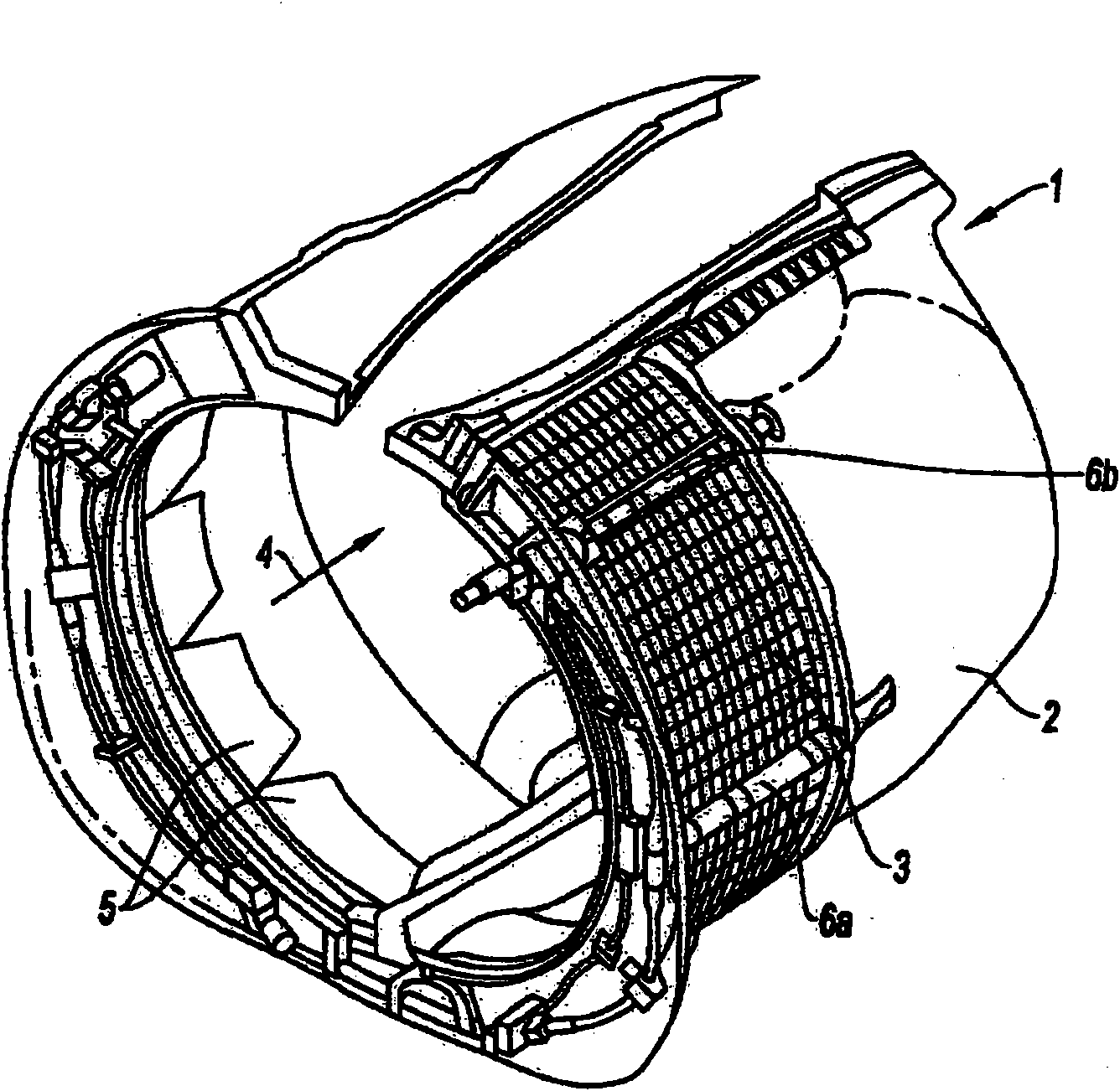
[0039] A thrust reverser 1 of the cascade type generally comprises a structure comprising two semicircular moving cowls 2 that can slide along guide rails (not shown) to deflect the blades of the blades. The grid is exposed, and said deflecting vanes are arranged between the moving cowl 2 and the section through which the airflow to be deflected passes.

[0040] Partition doors are provided inside the structure so that they can pivot and move from a position where they do not block the air flow channel 4 to a position where they b...


PUM


Abstract

The present invention relates to a thrust reverser for a jet engine nacelle comprising at least one movable cowl (2) mounted on a fixed reverser structure between a closed position, in which they provide the nacelle with aerodynamic continuity and deactivate means for deflecting at least part of the air flow, and an open position in which they open a passage in the nacelle and activate said deflection means, each movable cowl being able to be moved between these two positions by at least one actuating means (6a, 6b), characterized in that the actuating means are combined with at least one means (10) for mechanically braking said actuating means.

Description

technical field [0001] The invention relates to a cascade-type thrust reverser for a jet engine nacelle. Background technique [0002] The purpose of the thrust reverser is to increase the braking capability of the aircraft when the aircraft is on the ground by redirecting at least a portion of the thrust generated by the jet engine forward. During this phase, the reverser closes the gas lance nozzles and directs the jet of air from the engine towards the front of the nacelle, thereby generating a counter-thrust that participates in the braking of the wheels of the aircraft. [0003] The means used to redirect the flow vary according to the type of reverser. In all cases, however, the structure of the reverser includes a moving cowl movable between a deployed position on the one hand and a retracted position on the other hand, in which position the cowl is in the A channel for deflecting the airflow is deployed in the nacelle, which is blocked by the fairing in the retract...

Claims


Application Information

Patent Timeline
Patent Type & Authority Applications(China)
IPC IPC(8): F02K1/72F02K1/76
CPCF02K1/72F02K1/763
Inventor 伯努瓦·库比亚克
Owner AIRCELLE
Why Eureka
Try Eureka