Intelligent water saving toilet and intelligent flushing control method

A smart toilet technology, applied in the field of sanitary ware, can solve problems such as large randomness of human operation, inability to automatically control flushing time and flushing volume, toilet leakage, etc., and achieve the effects of reducing mechanical failures, saving space, and saving water resources

Inactive Publication Date: 2008-10-22
赵丕君
View PDF1 Cites 10 Cited by
  • Summary
  • Abstract
  • Description
  • Claims
  • Application Information

AI Technical Summary

Problems solved by technology

[0004] The purpose of the present invention is to address the above-mentioned defects in the existing toilet flushing structure, and provide an intelligent water-saving toilet and an intelligent flushing control method, which can overcome the leakage of the existing toilet, the large randomness of human operation, and the inability to automatically control the flushing time and flushing time. For the problem of water volume, the invention can not only completely solve the phenomenon of toilet water leakage, but also realize automatic flushing of the toilet according to the required water volume, and keep the toilet in a state of no water accumulation in the water tank when it is not in use

Method used


Image

  • Intelligent water saving toilet and intelligent flushing control method
  • Intelligent water saving toilet and intelligent flushing control method

Examples


Embodiment 1

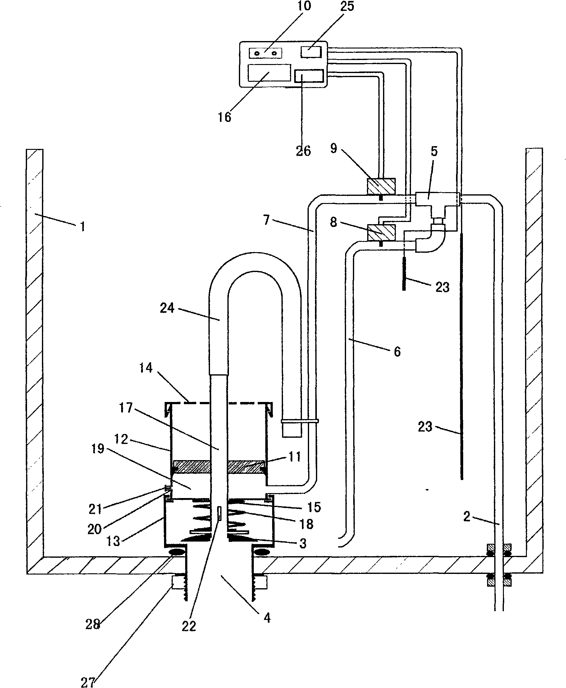
[0034] The intelligent water-saving toilet includes a water tank 1 and a water inlet pipe 2, a drain valve 3, and a water outlet 4 in the water tank 1. The water inlet pipe 2 is connected to the water injection pipe 6 and the pressure pipe 7 through a tee 5; the connection between the pressure pipe 7 and the drain valve 3 A hydraulic cylinder for opening and closing the drain valve 3 is arranged between them. The purpose of the tee 5 is to allow the water in the water inlet pipe 2 to enter the water injection pipe 6 and the drain pipe, and other structures / mechanisms to achieve this purpose are equally applicable. The water injection pipe 6 and the pressure pipe 7 are respectively provided with a water injection electric valve 8 and a drainage electric valve 9, and are electrically connected with the infrared controller.

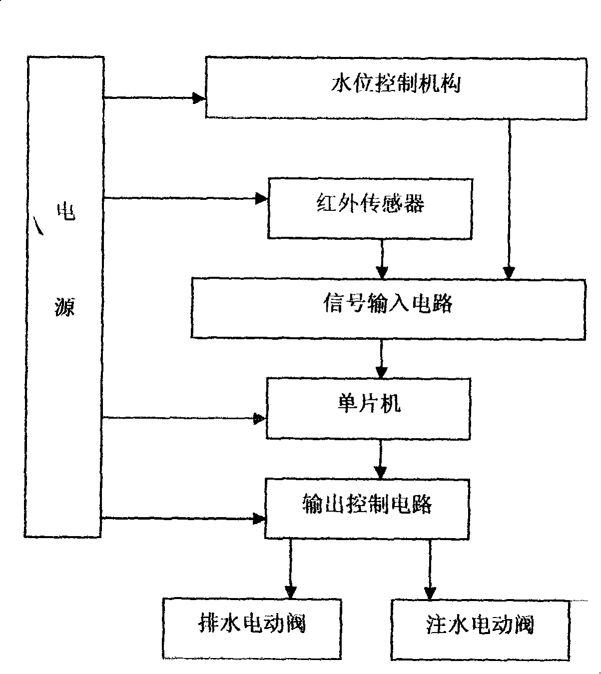
[0035] Infrared controller comprises infrared sensor 10, single-chip microcomputer 16, power supply 26, output control circuit 25, and infrared sensor is co...

Embodiment 2

[0038] The hydraulic cylinder of the intelligent water-saving toilet of the present invention includes a cylinder body 12 with a piston 11 disposed therein and a valve seat 13 located at the drain outlet 4 at the lower part of the cylinder body 12, and the valve seat 13 is installed at the drain outlet 4 of the water tank 1 . The upper end of the cylinder body 12 is provided with a cylinder cover 14 and the lower end is provided with a cylinder bottom 15 . The piston 11 is connected with a connecting rod 17, and the connecting rod 17 passes downward through the cylinder bottom 15 to connect with the drain valve 3 at the drain port 4, and a spring 18 is arranged between the drain valve 3 and the cylinder bottom 15; a sealing ring is embedded on the periphery of the piston A sealed hydraulic cavity 19 is formed between the cylinder bottom 15 and the periphery of the valve seat 13 is airtight. The upper end of the valve seat 13 is connected with the cylinder body 12. The valve se...

Embodiment 3

[0040] In order to make the drain valve 3 and the piston 11 return to their original positions after flushing, a pressure relief hole 20 is set on the outer wall of the hydraulic chamber 19 of the cylinder body 12, and the water in the hydraulic chamber 19 flows to the cylinder through the pressure relief hole 20. Outside the body 12, under the action of the elongation force of the spring 18, the drain valve 3 recloses the drain port 4, and the pressure relief hole 20 is provided with a flow control knob 21 to control the pressure relief speed.


PUM


Abstract

The invention discloses an intelligent water-saving closestool and an intelligent toilet-flushing control method to overcome the problems that the prior closestool has water leakage and great randomness of manual operation and can not automatically control flushing time and flushing quantity. The intelligent water-saving closestool comprises a water tank as well as a water inlet pipe, a drain valve and a drain opening arranged inside the water tank, wherein the water inlet pipe is connected with a water injection pipe and a pressure pipe through a teejunction; a hydraulic cylinder which is used to open and close the drain valve is arranged between the pressure pipe and the drain valve; the water injection pipe and the pressure pipe are respectively provided with a water injection electric valve and a drain electric valve, and are in electrical connection with an infrared sensor through a signal input / output circuit and an output control circuit. The intelligent water-saving closestool and the intelligent toilet-flushing control method not only can completely solve the water leakage phenomenon of a closestool, but also can realize automatic toilet flushing according to required water quantity; moreover, the closestool and the method can keep the water tank in a seeper-free state when the closestool is not used.

Description

technical field [0001] The invention belongs to the field of sanitary ware, in particular to a toilet, in particular to a toilet water tank structure and an intelligent flushing control method. Background technique [0002] Present known sitting type toilet all adopts water tank to store water, and a lever mechanism is established in the water tank, and its one end is connected with control valve, and the other end is connected with rubber drain valve. The control valve can be a mechanical button or an electric button. The mechanical button method is to lift the lever through artificial force, and the electric button is to drive the lever to run by starting the motor. When going to the toilet, the human-operated control valve (manual or electric) uses a mechanical lever to lift the drain valve to flush the toilet, and can realize flushing with large or small water by controlling the height of the lifted drain valve; after flushing, the floating ball sinks, and the water inle...

Claims


Application Information

Patent Timeline
Patent Type & Authority Applications(China)
IPC IPC(8): E03D5/10E03D1/30
Inventor 赵丕君
Owner 赵丕君
Why Eureka
Try Eureka