
Buzzer test separator

A technology for testing sorting machines and buzzers, which is applied in sorting and other directions, can solve the problems of high misjudgment rate and the inability of testing equipment to improve the testing speed, etc., and achieve the effects of high testing accuracy, simple structure, and accurate nesting

Inactive Publication Date: 2013-04-24
肇庆信泰机电科技有限公司
View PDF0 Cites 0 Cited by
  • Summary
  • Abstract
  • Description
  • Claims
  • Application Information

AI Technical Summary

Problems solved by technology

[0021] In order to solve the problem that the existing test equipment cannot increase the test speed and the misjudgment rate is high, the present invention proposes an automated, practical, high-efficiency, and low misjudgment rate buzzer chip test sorting machine

Method used


Image

  • Buzzer test separator
  • Buzzer test separator
  • Buzzer test separator

Examples


Embodiment Construction

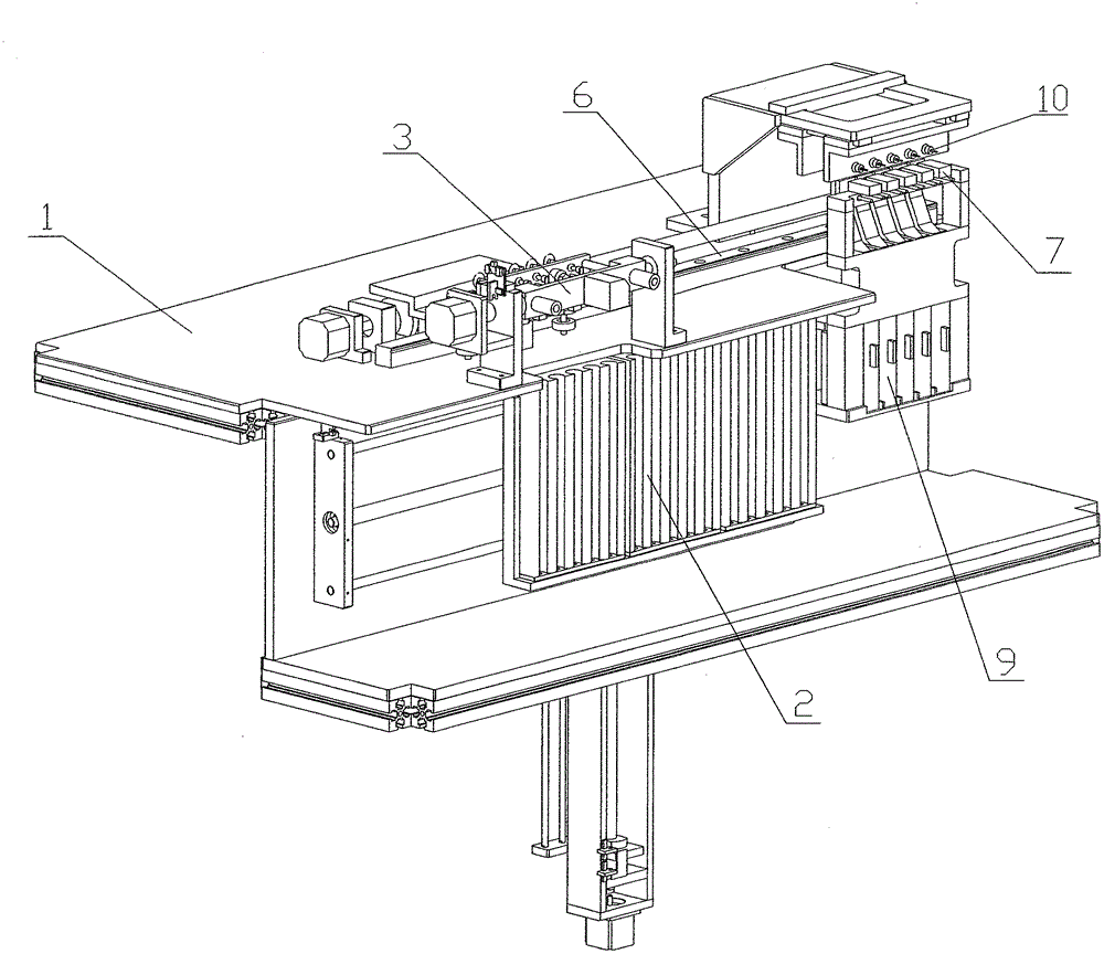
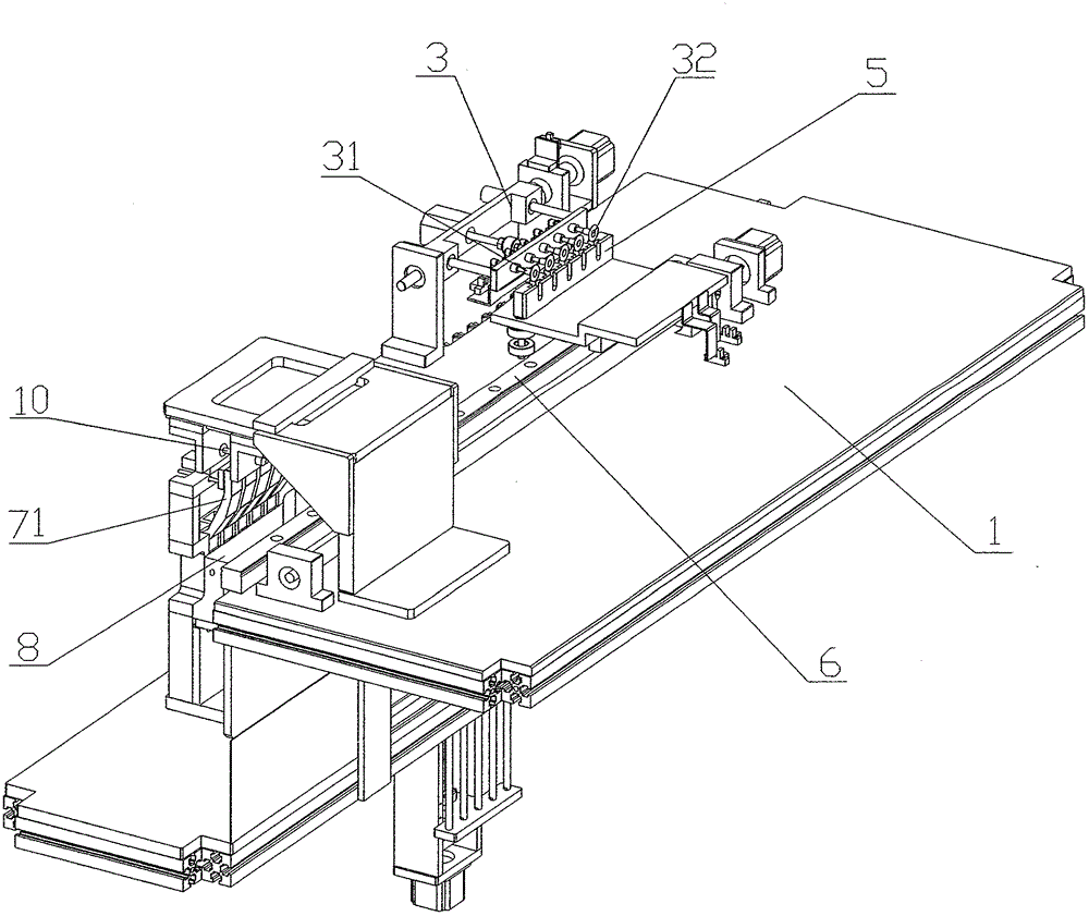
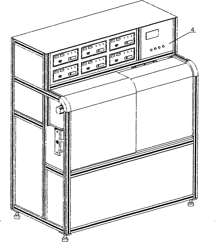
[0045] figure 1 , Figure 4 , Figure 5 , Figure 6 Schematic diagram of the appearance, structure and front view of the buzzer test sorter, including the frame, and three sets of feeding boxes installed on the frame, rotating feeding arm, U-shaped positioning groove, guide rail, test needle, waste bin, Qualified product warehouse, discharge hopper, console.

[0046]The three groups of feeding boxes 2 are hollow cylindrical structures with gaps. There are fifteen in total, five in each group. They are switched by stepping motors. One group of feeding boxes is in working state, and the other two groups of feeding boxes are in loading State; there is a ejector rod at the bottom of the feeding box, and the stepping motor controls the lifting of the ejector rod.

[0047] Five suction heads 31 are set on the rotating feeding arm 3, see Figure 5 , Figure 7 , Figure 9 , The suction head is guided by linear bearings and spring buffer structure. The rotating feeding arm can b...


PUM


Abstract

The invention relates to a buzzer test separator, belonging to the manufacturing field of electronic component test equipment. The separator comprises a rack, three groups of feeding boxes, a rotatable feeding arm, a U-shaped locating slot, a guide rail, test needles, a waste cabin, a qualified product cabin, a discharging hopper and a console, wherein the rotatable feeding arm with rotation amplitude of 0-90 degrees is provided with a material absorbing head to facilitate the absorption and delivery of a buzzer; the U-shaped locating slot with functions of vertical blanking and precise location can reciprocate along the guide rail below the material absorbing head and the test needles; the feeding box is a hollow cylindrical box with a gap, and three groups of feeding boxes work alternatively with high efficiency; the test needles arranged horizontally are used for vertical test with higher test accuracy than horizontal test; and the flexible discharging hopper is controlled by a discharging cylinder. The invention has the advantages of simple structure, accurate discharging and high reliability and practicability.

Description

technical field [0001] The invention relates to the field of manufacturing electronic component testing equipment, in particular to a testing and sorting machine for piezoelectric ceramic buzzer chips. Background technique [0002] The piezoelectric ceramic buzzer is a sounding element composed of a piezoelectric ceramic sheet and a metal substrate such as a copper sheet. It has the characteristics of thin thickness, light weight, clear pronunciation, anti-electromagnetic interference, and low power consumption; due to its non-contact Point, so no noise, high reliability. Widely used in various electroacoustic occasions, such as communication products, industrial instruments, household appliances and alarms: such as electronic clocks, car speakers, audio, communications, remote sensing, calculators, electronic toys and other products. [0003] At present, the testing and sorting work in the production process of piezoelectric ceramic buzzers is mainly performed manually, wh...

Claims


Application Information

Patent Timeline
Patent Type & Authority Patents(China)
IPC IPC(8): B07C5/344
Inventor 梁耀国吴忻生冯幸泉谢广裕江玉娟
Owner 肇庆信泰机电科技有限公司
Learn More